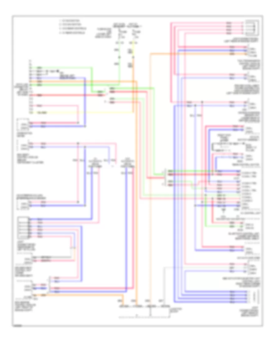
COMPUTER DATA LINES
Computer Data Lines Wiring Diagram for Nissan Maxima SV 2010
List of elements for Computer Data Lines Wiring Diagram for Nissan Maxima SV 2010:
- (on steering column) steering angle sensor
- (right kick panel) j/c b21
- A/c & av switch assembly
- A/c auto amplifier
- Abs actuator & electric unit (control unit) (right rear corner of engine compt)
- Air bag diagnosis sensor unit (under rear of center console)
- Av control unit
- B128
- B132 (right "c" pillar)
- B403
- Bcm (body control module) (behind instrument cluster)
- Can h2
- Can l2
- Can-h
- Can-l
- Combination meter
- Connector (below left side of dash)
- Data link
- Diag-k
- Driver's seat control unit (under driver's seat)
- E10
- E45
- E46
- E50
- Ecm (engine control module) (left front of engine compt)
- Fuse 10a
- Fuse block (j/b) (lower left side of dash)
- Hot at all times
- Hot in on or start
- Ipdm e/r (intelligent power distribution module engine room) (left side of engine compt)
- Joint connector b01 (near base of left "b" pillar)
- Joint connector e03 (left rear of engine compt)
- Joint connector e04 (left rear of engine compt)
- Junction block
- K-line
- M can h
- M can h trm
- M can l
- M can l trm
- M can2 h
- M can2 l
- M137
- M163
- M35
- M46
- M61 (behind left side of dash)
- Nca
- Pnk
- Rear control switch
- Red
- Tcm (transmission control module) (left front of engine compt)
- W/ automatic drive positioner
- W/ navigation
- W/ rear controls
- W/o automatic drive positioner
- W/o navigation
- W/o rear controls
 English