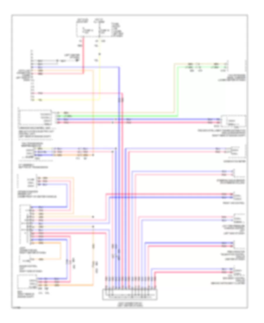
COMPUTER DATA LINES
Computer Data Lines Wiring Diagram for Nissan NV3500 HD SV 2014
List of elements for Computer Data Lines Wiring Diagram for Nissan NV3500 HD SV 2014:
- (left center of dash) m61
- 21g
- 4.0l
- 5.6l
- A/t assembly (bottom of transmission)
- Abs actuator & electric unit (control unit) (left rear of engine compt)
- Abs/tcs/vdc control unit
- Air bag diagnosis sensor unit (under front of center console)
- Bcm (body control module) (behind instrument cluster)
- Can-h
- Can-l
- Combination meter
- Cpu
- Data link connector (under left side of dash)
- E122
- E152
- E16
- E55
- E77
- Ecm (right rear of engine compt)
- F14
- F502
- Front air control
- Fuse 12 10a
- Fuse 19 10a
- Fuse block (j/b) (lower left end of dash)
- Hot at all times
- Hot in on or start
- Ipdm e/r (intelligent power distribution module engine room) (right rear of engine compt)
- Joint connector m01 (left center of dash)
- Joint connector m02 (right center of dash)
- K-line
- Low tire pressure warning control unit (left end of dash)
- M108
- M18
- M31
- M39
- M78
- Pnk
- Pre-wiring for telematics control module (center of dash)
- Red
- Sonar control unit (right side of dash)
- Steering angle sensor (on steering column)
- Tcm (transmission control module)
- Yaw rate/side/ decel g-sensor (lower center of dash)
- Yg can-h
- Yg can-l
 English