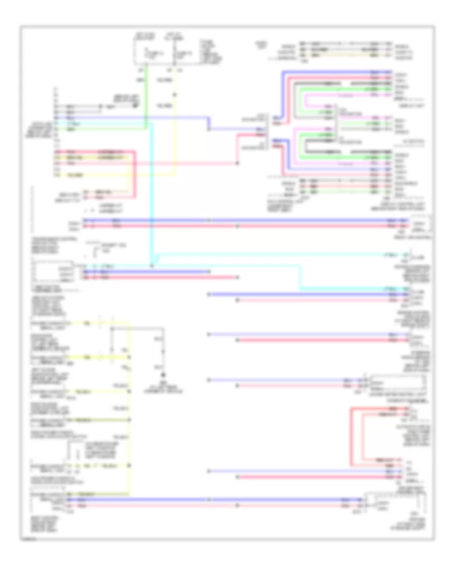
COMPUTER DATA LINES
Computer Data Lines Wiring Diagram for Nissan Quest 2006
List of elements for Computer Data Lines Wiring Diagram for Nissan Quest 2006:
- (4-speed a/t)
- (behind left end of dash) m57
- 4-speed a/t
- 5-speed a/t
- Abs actuator & electric unit (control unit) (at right rear of engine compt)
- Abs/tcs/vdc control unit
- Air bag diagnosis sensor unit (behind right end of dash)
- Audio rx
- Audio tx
- Audio unit
- Automatic drive positioner control unit (behind left side of dash)
- Av switch
- B143
- B60
- B66 (at left rear corner of vehicle)
- Back door control unit (at left rear corner of vehicle)
- Body control module (bcm) (behind left side of dash)
- Bus +
- Bus -
- Bus shield
- Can-h
- Can-l
- Combination meter
- Cpu
- Data link connector (below left side of dash)
- Diag-k
- Display control unit (behind right end of dash)
- Display unit
- Driver seat control unit
- E121
- E16
- Engine control module (ecm) (at right rear of engine compt)
- Except vdc
- Front air control
- Fuse 12 10a
- Fuse 19 15a
- Fuse block (j/b) (behind left side of dash)
- Hot at all times
- Hot in on or start
- Ipdm e/r (at right side of engine compt)
- K-line
- Left sliding door control unit (behind left rear quarterpanel)
- M18
- M23
- M35
- M41
- M45
- M50
- M95
- Main power window & door lock/unlock switch
- Navi control unit (under right front seat)
- Nca
- P107
- Pnk
- Power window serial link
- Red
- Right power window & door lock/unlock switch
- Right sliding door control unit (at right "c" pillar)
- Shield
- Sss in (rx)
- Sss out (tx)
- Steering angle sensor (w/ vdc) (behind left side of dash)
- Transmission control module (tcm) (behind right side of dash)
- Unified meter control unit
- Vdc
- W/ navigation
- W/o navigation
- W/o rear power vent windows w/ rear power vent windows
 English