CRUISE CONTROL
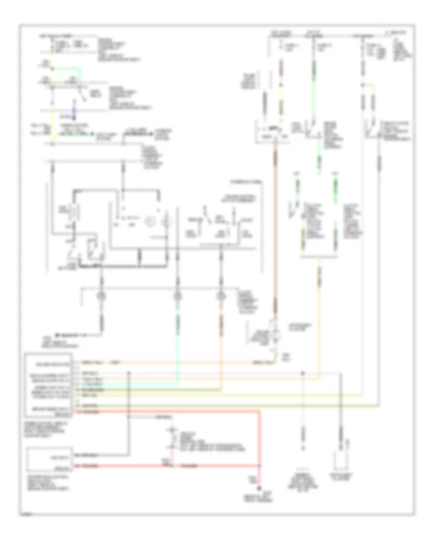
Cruise Control Wiring Diagram for Mazda B4000 SE 1995
List of elements for Cruise Control Wiring Diagram for Mazda B4000 SE 1995:
- (1995) (1996, 1997)
- (1995) (1996, 97)
- (1997)
- (left side of radiator support)
- (rear of left front fender)
- 10a 7.5a
- 15a
- 7.5a
- A/t
- Accel
- Anti-theft system
- Brake on/off (boo) switch (on brake pedal support)
- Brake on/off sw in
- Brake press input
- C 1995 vftc
- C-215
- Clock spring assembly (top of steering column)
- Clutch pedal position (cpp) switch (top of clutch pedal support)
- Clutch pedal position (cpp) switch jumper (left of steering column)
- Coast
- Cruise control indicator (1997)
- Cruise control switch assembly
- Cruise indicator
- Deactivator switch (left side of engine compartment)
- Engine compartment fuse/relay box (left side of engine compartment)
- Engine compartment fuse/relay box (left side of enigne compartment)
- Fuse 10
- Fuse 11
- Fuse 13
- Fuse 4 fuse 15 20a
- G104
- G108
- General electronic module (gem) (behind center of i/p)
- Ground
- Head
- Horn relay
- Horn switches
- Horns system
- Hot at all times
- Hot in run
- Hot in run or start
- I/p fuse panel (behind left side of i/p)
- Instrument cluster
- Interior lights system
- M/t
- Main light switch
- Nca
- Off
- Ohms
- Only
- Park
- Power (hot in run)
- Powertrain control module (pcm) (right rear of engine compartment)
- Pulse width dimming module
- Resume
- Set/
- Speed cont sw gnd
- Speed cont sw in
- Speed control servo/ amplifier assembly (right side of engine compartment)
- Steering wheel
- Vehicle speed input
- Vehicle speed sensor (vss) (4x2: left rear of transmission 4x4: left rear of transfer case)
- Vss input
 English