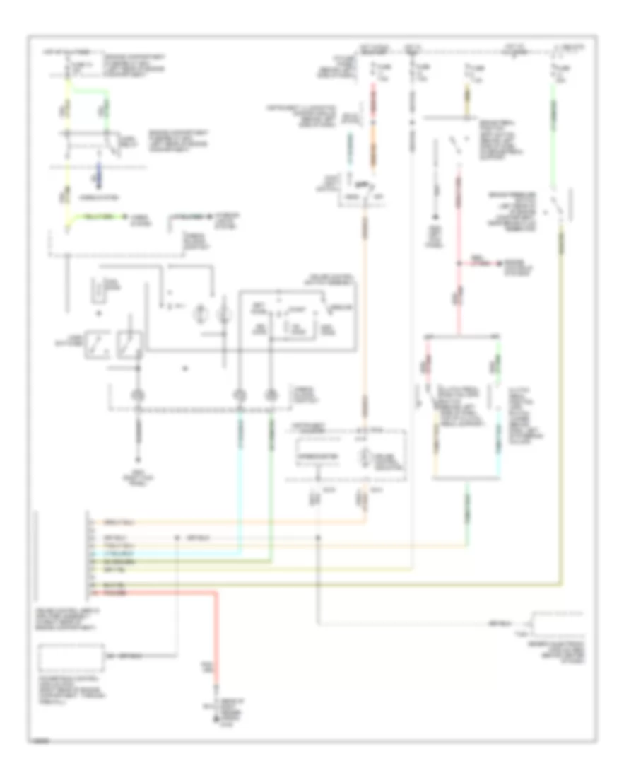
CRUISE CONTROL
Cruise Control Wiring Diagram for Mazda B4000 TL 2000
List of elements for Cruise Control Wiring Diagram for Mazda B4000 TL 2000:
- (rear of right fender apron) g105
- A/t
- Accel
- Airbag sliding contact
- Brake pedal position (bpp) switch (behind left side of dash, on brake pedal support)
- Brake pressure switch (left rear of of engine compartment, near brake fluid reservoir)
- C 1995 vftc
- C214
- C215
- Clutch pedal position (cpp) switch (behind left side of dash, top of clutch pedal support)
- Clutch pedal position (cpp) switch jumper (behind dash, left of steering column)
- Coast
- Cruise control indicator
- Cruise control servo/ amplifier assembly (in right rear of engine compartment)
- Cruise control switch assembly
- Engine compartment fuse/relay box (left rear of engine compartment)
- Engine controls systems
- Fuse 10 15a
- Fuse 20a
- Fuse 7.5a
- G200 (left kick panel)
- G203 (right kick panel)
- Generic electronic module (gem) (behind center of dash)
- Head
- Horn relay
- Horn switches
- Horns system
- Hot at all times
- Hot in run
- Hot in run or start
- I/p fuse panel (behind left side of dash)
- Instrument cluster
- Instrument illumination dimming module (behind left side of dash)
- Interior lights system
- M/t
- Main light switch
- Off
- Ohms
- Park
- Powertrain control module (pcm) (right rear of engine compartment, through firewall)
- Resume
- Set/
- Solid state
- Speedometer
- T-224
 English