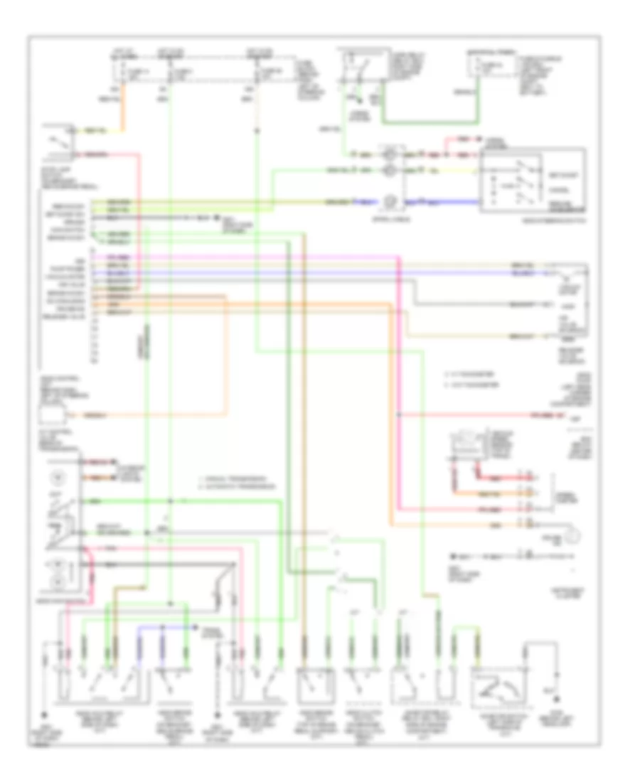
CRUISE CONTROL
Cruise Control Wiring Diagram for Nissan 200SX 1998
List of elements for Cruise Control Wiring Diagram for Nissan 200SX 1998:
- (a/t)
- 16n
- 16s
- A/t
- A/t control valve (rear of transmission)
- Above brake pedal) (a/t)
- Above clutch pedal) (m/t)
- Air valve
- Air valve solenoid
- Ascd brake switch (on bracket,
- Ascd brake switch (top of brake
- Ascd clutch switch (on bracket,
- Ascd control unit (behind dash, left of steering column)
- Ascd hold relay (behind left side of dash) (a/t)
- Ascd hold relay (behind left side of dash) (m/t)
- Ascd main switch
- Ascd pump (left rear corner of engine compartment)
- Ascd steering switch
- Automatic transmission
- Brake n/c sw
- Brake n/o sw
- Cancel
- Compartment)
- Cruise ind
- Ecm (below center of dash)
- Fuse & fusible link box (left front of engine compt, next to battery)
- Fuse 14 15a
- Fuse 25 10a
- Fuse 42 10a
- Fuse 8 7.5a
- Fuse block (behind dash, left of steering column)
- G106 (behind left headlamp)
- G201 (right side
- G201 (right side of dash)
- Ground
- Horn relay (relay box, right side of engine compt)
- Horns system
- Hot at all times
- Hot in on or start
- Inhibitor relay (relay box, right side of engine
- Inhibitor switch (left side of transaxle)
- Instrument cluster
- Interior lights system
- M/t
- Main switch
- Manual transmission
- Od cancle sig
- Of dash)
- Off
- Pedal support) (m/t)
- Pnk
- Pump power
- R p
- Red
- Red/gn
- Red/yl
- Release valve
- Release valve solenoid
- Res/acc sw
- Resume/ accelerate
- Set/coast
- Set/coast sw
- Speed- ometer
- Spiral cable
- Stop lamp switch (on bracket, above brake pedal)
- Trans. system
- Vacuum motor
- Vehicle speed sensor (top of trans.)
- Vsp
- Vss
- W tachometer
- W/o tachometer
 English