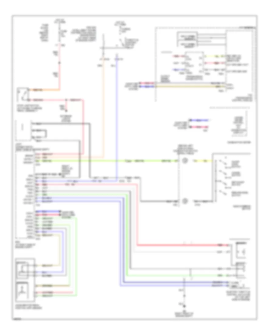
CRUISE CONTROL
Cruise Control Wiring Diagram for Nissan Armada SV 2014
List of elements for Cruise Control Wiring Diagram for Nissan Armada SV 2014:
- (behind left side of dash) combination switch (spiral cable)
- (right front of engine compt) e9
- 68g
- 69g
- A/t assembly
- Accelerator pedal position (app) sensor
- Aps1
- Aps2
- Ascd steering switch
- Ascdsw
- Avcc
- Avcc2
- Brake
- C1 (vin)
- C2 (vout)
- C3 (gnd) f506
- Can-h
- Can-l
- Cancel switch
- Close
- Combination meter
- Computer data lines system
- E119
- E122
- E152
- E16
- E9 (right front of engine compt)
- Ecm (at right side of engine compt)
- Electric throttle control actuator (at top left side of engine)
- Exterior lights system
- F14
- F32
- F502
- F503
- F505
- F54
- Fuse 10a
- Fuse 52 20a
- Fuse block (j/b) (behind right end of dash)
- Gnd
- Gnd-a
- Gnd-a2
- Hot at all times
- Input speed sensor 1
- Input speed sensor 2
- Ipdm e/r (intelligent power distribution module engine room) (at right rear of engine compt)
- Joint connector f01 (right side of engine compt)
- M102
- M24
- M30
- M31
- M60
- Motor 1
- Motor 2
- Motrly
- On/off (main) switch
- Open
- Out spd sen gnd
- Out spd sen vout
- Output speed sensor
- Pnk
- Red
- Resume/accel switch
- Rev sen vin (or out spd sens pwr)
- Sensor 1
- Sensor 2
- Set/coast switch
- Stop lamp switch (attached to brake pedal assembly)
- Tcm (transmission control module)
- Throttle control motor relay
- Tps1
- Tps2
- Transmission range switch
- Unified meter control unit (w/ information display)
- Vmot
 English