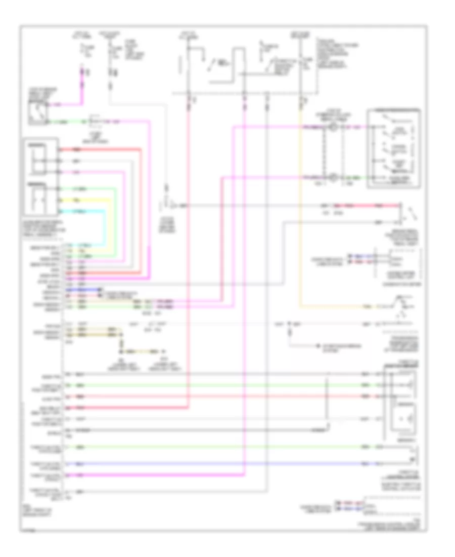
CRUISE CONTROL
Cruise Control Wiring Diagram for Nissan Rogue SL 2014
List of elements for Cruise Control Wiring Diagram for Nissan Rogue SL 2014:
- (top of brake pedal assy) stop lamp switch
- (top of steering column) spiral cable
- (under left headlight assy)
- 16r
- 38j
- 41j
- 50j
- Accel/res switch
- Accelerator pedal position sensor (top of accelerator pedal assembly)
- Acsd steering switch
- Aps1
- Aps2
- Ascdsw
- Avcc-tps
- Bncsw
- Brake pedal position switch (top of brake pedal assy)
- Can-h
- Can-l
- Cancel
- Coast/ set
- Combination meter
- Computer data lines system
- E15
- E152
- E16
- E28
- Ecm (left front of engine compt)
- Ecm relay
- Ecm relay (self shut off)
- Electric throttle control actuator
- F33 e19
- F35
- F42
- F51
- F52
- Fuse 10a
- Fuse 36 15a
- Fuse block (j/b) (left end of dash)
- Gnda-aps1
- Gnda-aps2
- Gnda-ascdsw
- Gnda-tps
- Hot at all times
- Hot in acc or on
- Hot in on or start
- Ipdm e/r (intelligent power distribution module engine room) (left side of engine compt)
- J/c e01 (left end of dash)
- J/c m18 (lower center of dash)
- M30
- M31
- M31 e152
- M68
- M90
- Main switch
- Pnk
- Pnp sig
- Red
- Sens pwr sply
- Sensor 1
- Sensor 2
- Shield
- Starting/charging system
- Stop lp sw
- Switch
- Tan
- Tcm (transmission control module) (left rear of engine compt)
- Throttle control motor
- Throttle control motor relay
- Throttle position sensor
- Transmission range switch (top left side of transmission)
- Unified meter control unit
- Vehcan-h
- Vehcan-l
 English