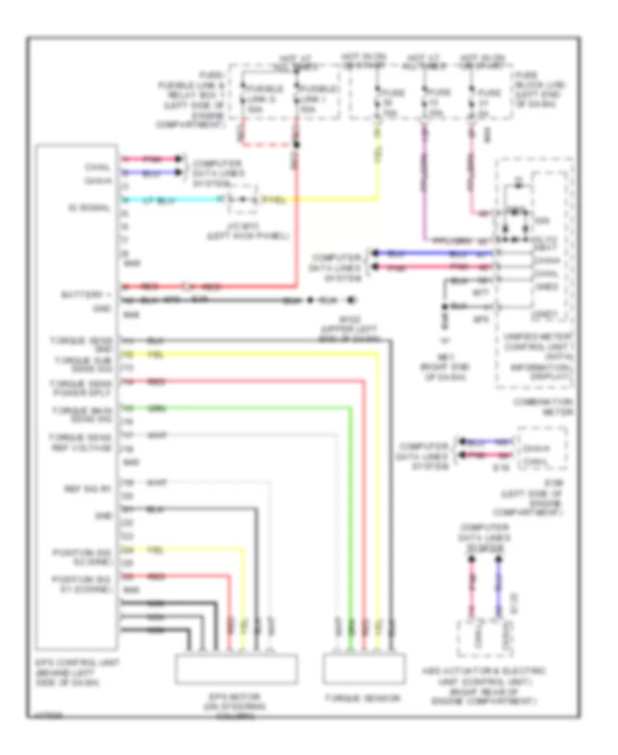
ELECTRONIC POWER STEERING
Electronic Power Steering Wiring Diagram for Nissan Rogue SL 2014
List of elements for Electronic Power Steering Wiring Diagram for Nissan Rogue SL 2014:
- (left side of engine compartment)
- 13p
- Abs actuator & electric
- Alvu sbat
- Battery +
- Can-h
- Can-l
- Combination meter
- Computer data lines system
- Control unit (with
- E125
- E16
- E36
- Ecm
- Eps
- Eps control unit (behind left side of dash)
- Eps motor (on steering column)
- Fuse 10a
- Fuse 5a
- Fuse block (j/b) (left end of dash)
- Fuse/ fusible link & relay box 1 (left side of engine compartment)
- Fusible link g 50a
- Fusible link i 50a
- Gnd
- Gnd1
- Gnd2
- Hot at all times
- Hot in on or start
- Ig signal
- Ign
- Information display)
- J/c m13 (left kick panel)
- M122 (upper left end of dash)
- M44
- M45
- M46
- M48
- M49
- M61 (right end of dash)
- M75
- M76
- M77
- Nca
- Pnk
- Position sig s1 (cosine)
- Position sig s2 (sine)
- Red
- Ref sig r1
- Torque main sens sig
- Torque sens
- Torque sens power sply
- Torque sens ref voltage
- Torque sensor
- Torque sub sens sig
- Unified meter
- Unit (control unit) (right rear of engine compartment)
 English