ELECTRONIC SUSPENSION
Electronic Suspension Wiring Diagram for Nissan Armada SE 2005
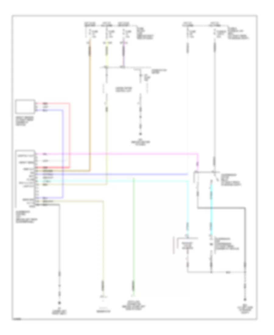
List of elements for Electronic Suspension Wiring Diagram for Nissan Armada SE 2005:
- Alt in
- B7 (under left front seat)
- Bat
- Ck susp ind
- Combination meter
- Comp rly out
- Compressor motor relay (at right front of engine compt)
- Data link connector (behind lower left side of dash)
- E24 (at left side of engine compt)
- Exh vlv out
- Exhaust valve solenoid
- Fuse & fusible link box (at right rear of engine compt)
- Fuse 10a
- Fuse block (j/b) (behind right end of dash)
- Fusible link g 30a
- Generator
- Gnd
- Height sens
- Height sensor (at right rear corner of vehicle)
- Hot at all times
- Hot in on or start
- Ign
- K-line
- Lamp out
- M39
- M61 (behind center of dash)
- Red
- Sens gnd
- Suspension air compressor (at right rear corner of vehicle)
- Suspension control unit (behind left rear quarterpanel)
- Unified meter control unit
- Vref out
 English