ENGINE PERFORMANCE
2.3L
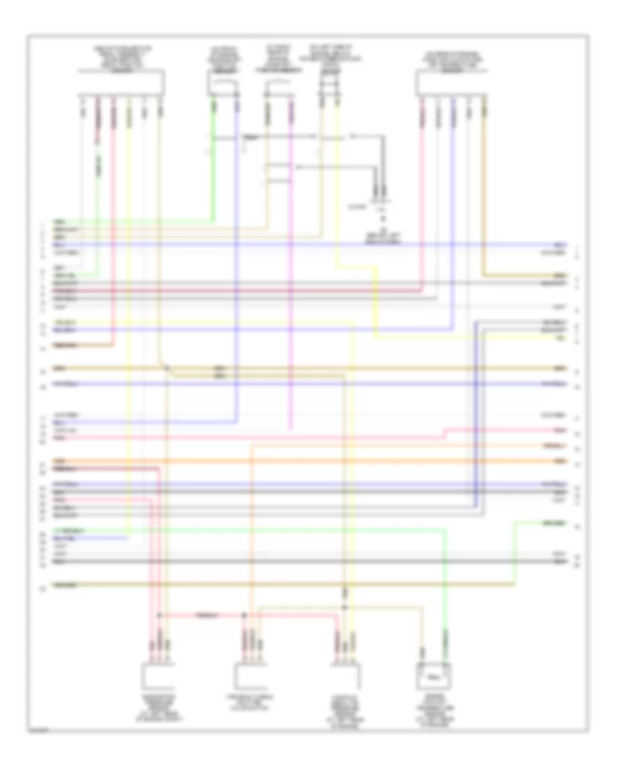
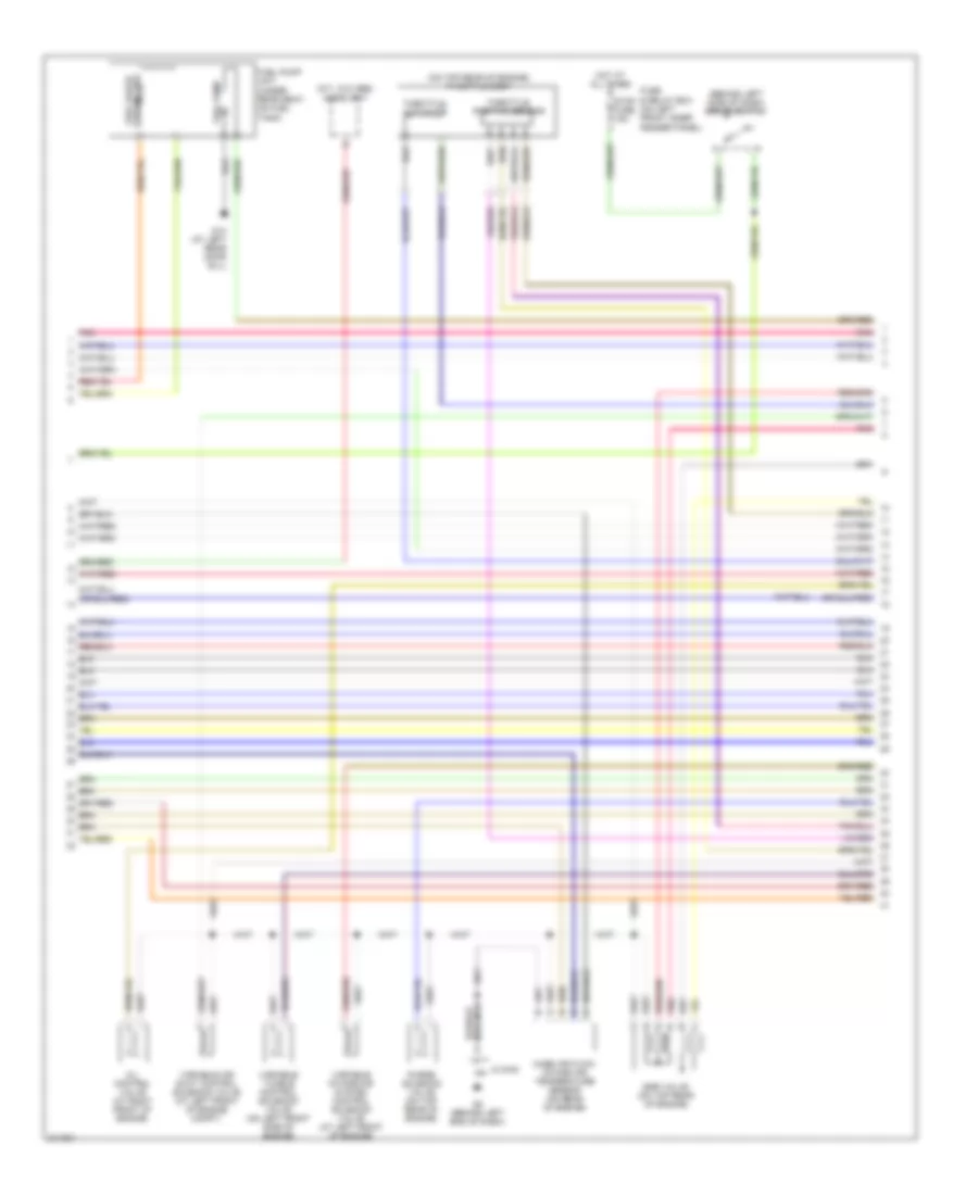
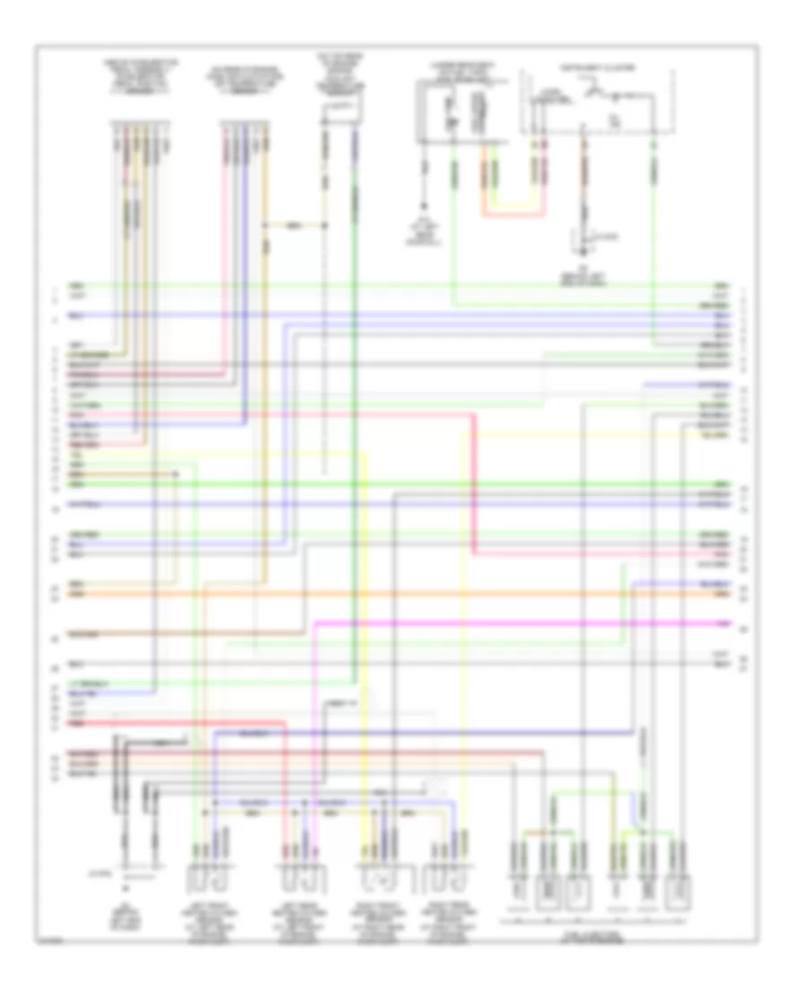
2.3L, Engine Performance Wiring Diagram, California (1 of 4) for Mazda 6 i 2005

List of elements for 2.3L, Engine Performance Wiring Diagram, California (1 of 4) for Mazda 6 i 2005:
- (on top rear of engine)
- Actuator throttle
- Air conditioning system
- Eng bar fuse 15a
- Etc fuse 7.5a
- Etc relay
- Fuel injectors (at top of engine)
- Fuel pump fuse 15a
- Fuse & relay box (on left front inner fender panel)
- G2 (behind left end of dash)
- Hot at all times
- Inj fuse 15a
- Jc g-02
- Main relay
- Pnk
- Powertrain control module (behind left side of dash)
- Starting/charging system
- Throttle body
- Throttle position sensor
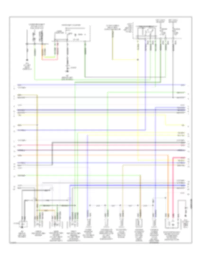
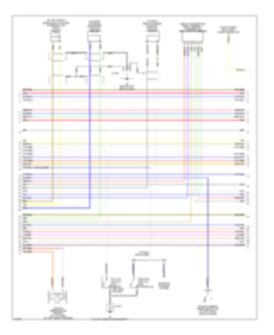
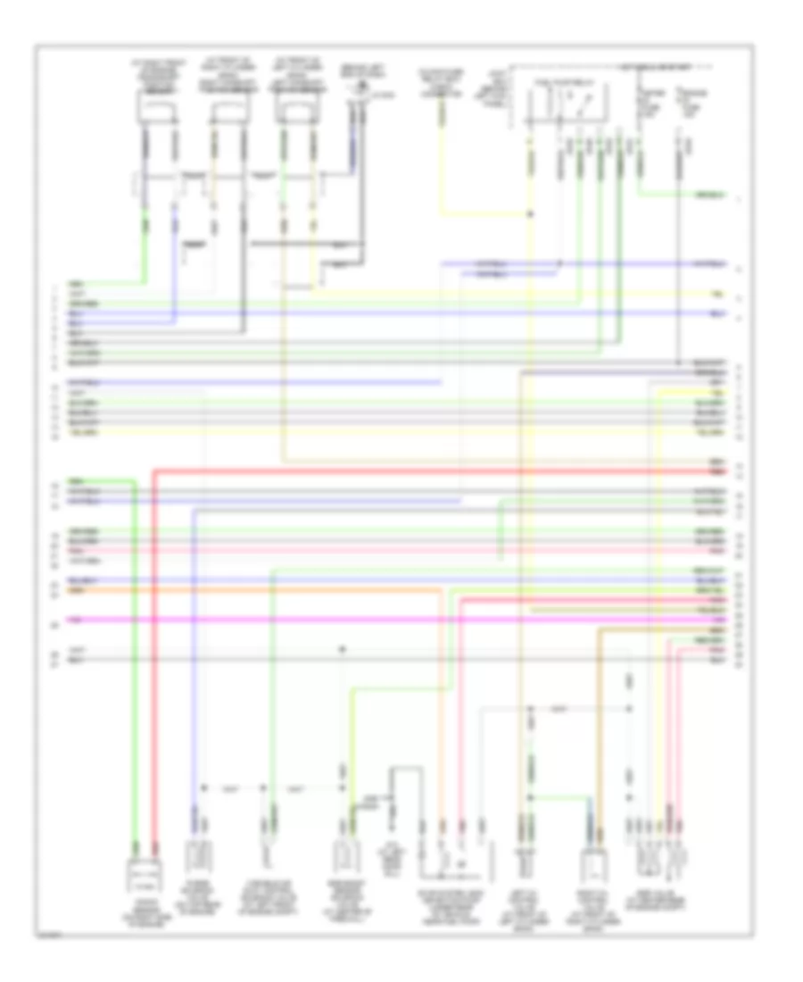
2.3L, Engine Performance Wiring Diagram, California (2 of 4) for Mazda 6 i 2005
List of elements for 2.3L, Engine Performance Wiring Diagram, California (2 of 4) for Mazda 6 i 2005:
- (above accelerator pedal assembly) accelerator pedal position sensor
- (at right rear of engine) camshaft position sensor
- (on front of engine) crankshaft position sensor
- (on left side of engine, below power steering pump) knock sensor
- (on rear of engine) mass air flow/intake air temperature sensor
- Barometric pressure sensor (at left rear of engine compt)
- Engine coolant temperature sensor (at left rear of engine)
- G2 (behind left end of dash)
- Jc g-02
- Manifold absolute pressure sensor (at left rear of engine)
- Nca nca
- Pnk
- Variable tumble shutter valve switch
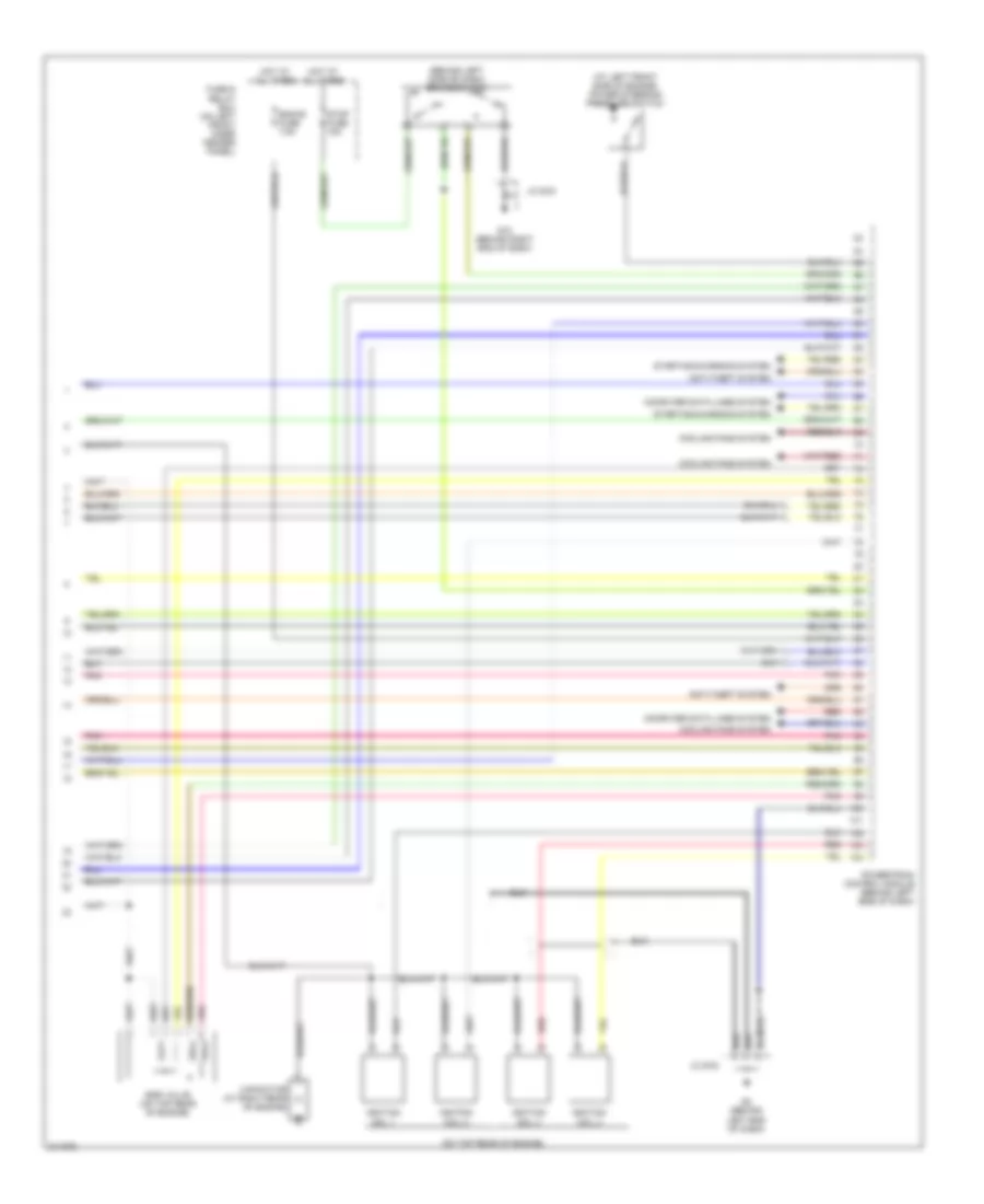
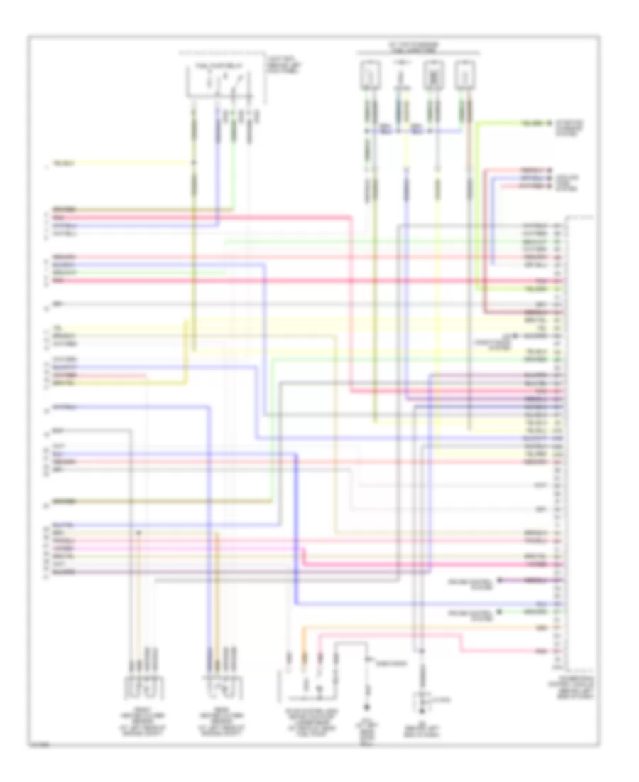
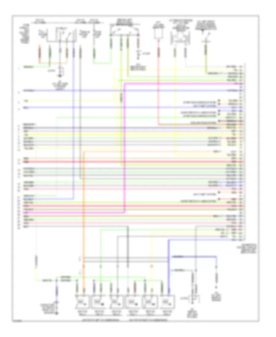
2.3L, Engine Performance Wiring Diagram, California (3 of 4) for Mazda 6 i 2005
List of elements for 2.3L, Engine Performance Wiring Diagram, California (3 of 4) for Mazda 6 i 2005:
- (behind left end of dash)
- (in main fuse & relay box) check connector
- (under rear seat, on fuel tank) fuel pump unit
- 5hb/wagon
- Engine ig fuse 15a
- Evap system leak detection pump (under rear of vehicle, near fuel pump)
- Front heated oxygen sensor (at left rear of engine compartment)
- Fuel pump
- Fuel pump relay
- G13 (at left rear door sill)
- G2 (behind left end of dash)
- Hot in run or start
- Instrument cluster
- Jb-01
- Jb-02
- Jb-05
- Jc g-02
- Joint box (behind left kick panel)
- Meter ig fuse 15a
- Micro computer
- Middle heated oxygen sensor
- Mil ind
- Nca
- Oil control valve (at right front of engine)
- Pnk
- Purge solenoid valve (on top rear of engine)
- Rear heated oxygen sensor (at left rear of engine compartment)
- Sender unit fuel gauge
- Variable air duct control solenoid valve (at left front of engine compt)
- Variable intake-air system control (at left front engine)
- Variable tumble control solenoid valve (on left front side of engine)
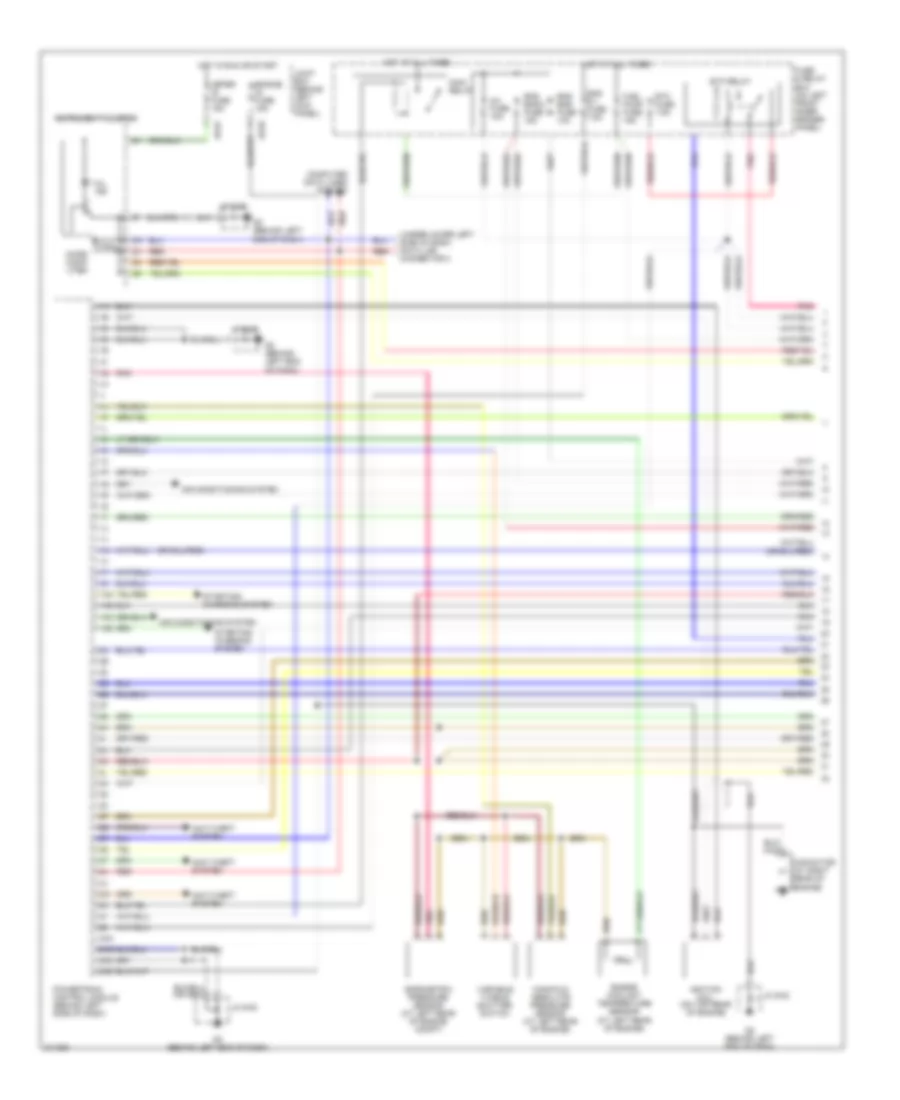
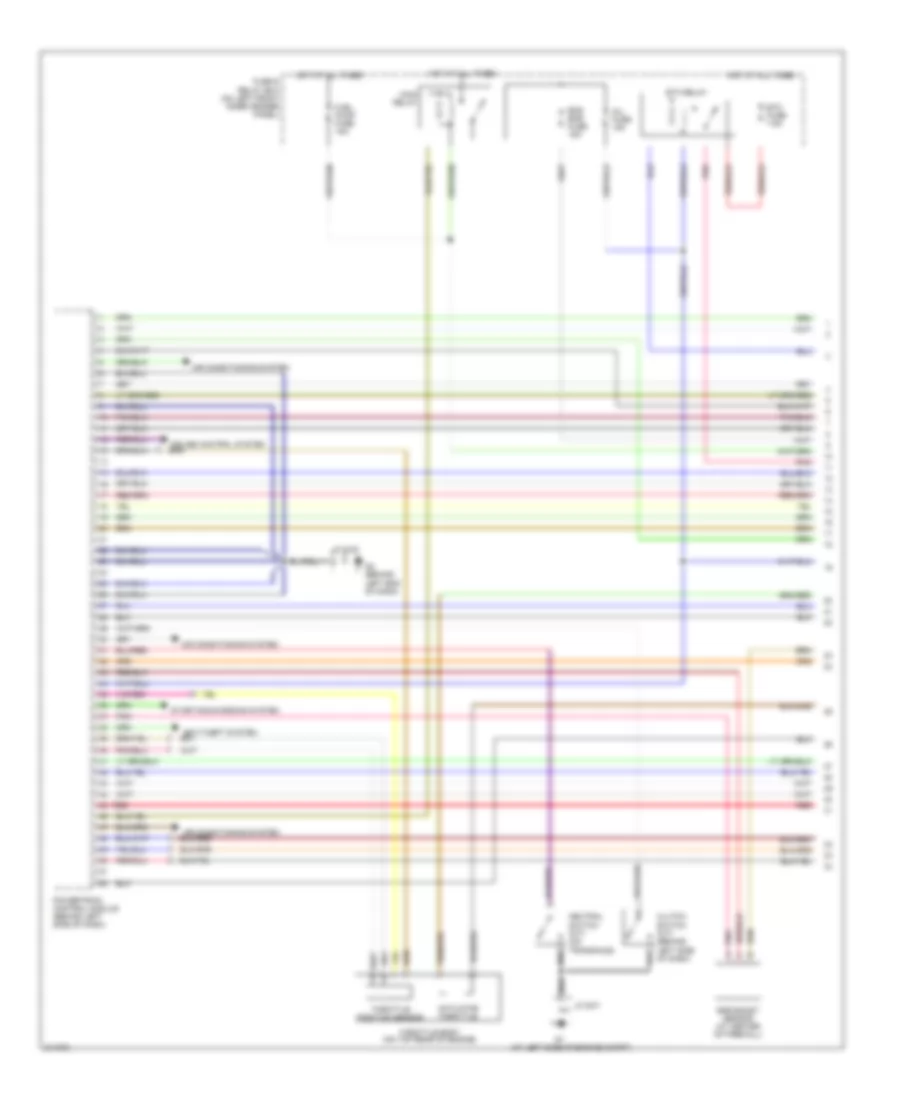
2.3L, Engine Performance Wiring Diagram, California (4 of 4) for Mazda 6 i 2005
List of elements for 2.3L, Engine Performance Wiring Diagram, California (4 of 4) for Mazda 6 i 2005:
- (at left front side of engine) power steering pressure switch
- (behind left side of dash) brake switch
- (on top rear of engine)
- Anti-theft system
- Capacitor (at right rear of engine)
- Computer data lines system
- Cooling fans system
- Egr valve (on top rear of engine)
- Eng+b fuse 7.5a
- Fuse & relay box (on left front inner fender panel)
- G10 (behind right end of dash)
- G2 (behind left end of dash)
- Hot at all times
- Ignition coil 1
- Ignition coil 2
- Ignition coil 3
- Ignition coil 4
- Jc g-02
- Jc g-03
- Pnk
- Powertrain control module (behind left side of dash)
- Red
- Starting/charging system
- Stop fuse 15a
2.3L, Engine Performance Wiring Diagram, Except California (1 of 4) for Mazda 6 i 2005
List of elements for 2.3L, Engine Performance Wiring Diagram, Except California (1 of 4) for Mazda 6 i 2005:
- (under lower left side of dash) data link connector 2
- 1aa
- 1ab
- 1ac
- 1ad
- 2aa
- 2ab
- 2ac
- 2ad
- Air conditioning system
- Anti-theft system
- Barometric pressure sensor (at left rear of engine compt)
- Capacitor (at right rear of engine)
- Computer data lines system
- Eng b + fuse 7.5a
- Eng bar 2 fuse 15a
- Eng bar fuse 10a
- Engine coolant temperature sensor (at left rear of engine)
- Engine ig fuse 15a
- Etc fuse 7.5a
- Etc relay
- Fuel pump fuse 15a
- Fuse & relay box (on left front inner fender panel)
- G2 (behind left end of dash)
- Hot at all times
- Hot in run or start
- Ignition coil (on top rear of engine)
- Inj fuse 15a
- Instrument cluster
- Jb-01
- Jb-02
- Jc g-02
- Joint box (behind left kick panel)
- Main relay
- Manifold absolute pressure sensor (at left rear of engine)
- Meter ig fuse 15a
- Micro comp- uter
- Mil ind
- Pnk
- Powertrain control module (behind left side of dash)
- Red
- Starting/ charging system
- Variable tumble shutter switch
2.3L, Engine Performance Wiring Diagram, Except California (2 of 4) for Mazda 6 i 2005
List of elements for 2.3L, Engine Performance Wiring Diagram, Except California (2 of 4) for Mazda 6 i 2005:
- (behind left side of dash) brake switch
- (m/t, w/o abs) audio unit
- (on top rear of engine) throttle body
- Egr valve (on top rear of engine)
- Fuel gauge sender unit
- Fuel pump
- Fuel pump unit (under rear seat, on fuel tank)
- Fuse & relay box (on left front inner fender panel)
- G13 (at left rear door sill)
- G2 (behind left end of dash)
- Hot at all times
- Jc g-02
- Mass air flow/ intake air temperature sensor (on rear of engine)
- Oil control valve (at right front of engine)
- Pnk
- Purge solenoid valve (on top rear of engine)
- Stop fuse 15a
- Throttle actuator
- Throttle position sensor
- Variable air duct control solenoid valve (at left front of engine compt)
- Variable intake-air system control solenoid valve (at left front of engine)
- Variable tumble control solenoid valve (on left front side of engine)
2.3L, Engine Performance Wiring Diagram, Except California (3 of 4) for Mazda 6 i 2005
List of elements for 2.3L, Engine Performance Wiring Diagram, Except California (3 of 4) for Mazda 6 i 2005:
- (above accelerator pedal assembly) accelerator pedal position sensor
- (at right rear of engine) camshaft position sensor
- (in main fuse & relay box) check connector
- (on front of engine) crankshaft position sensor
- (on left side of engine, below power steering pump) knock sensor
- A/t
- Clutch switch (m/t) (behind left side of dash)
- G1 (at left side of engine compt)
- G2 (behind left end of dash)
- Jc g-01
- Jc g-02
- M/t
- Nca
- Neutral switch (on transaxle)
- Pnk
- Power steering pressure switch (at left front side of engine)
- Starting/ charging system
- Vehicle speedometer sensor (m/t, w/o abs) (at left rear of engine)
2.3L, Engine Performance Wiring Diagram, Except California (4 of 4) for Mazda 6 i 2005
List of elements for 2.3L, Engine Performance Wiring Diagram, Except California (4 of 4) for Mazda 6 i 2005:
- (at top of engine) fuel injectors
- 3aa
- 4aa
- 4ab
- 4ac
- 4ad
- 5hb/wagon
- Air conditioning system
- Cooling fans system
- Cruise control system
- Evap system leak detection pump (under rear of vehicle, near fuel pump)
- Front heated oxygen sensor (at left rear of engine compt)
- Fuel pump relay
- G13 (at left rear door sill)
- G2 (behind left end of dash)
- Jb-02
- Jb-05
- Jc g-02
- Joint box (behind left kick panel)
- Pnk
- Powertrain control module (behind left side of dash)
- Rear heated oxygen sensor (at left rear of engine compt)
- Starting/ charging system
3.0L
3.0L, Engine Performance Wiring Diagram (1 of 4) for Mazda 6 i 2005
List of elements for 3.0L, Engine Performance Wiring Diagram (1 of 4) for Mazda 6 i 2005:
- (at left side of engine compt)
- Actuator throttle
- Air conditioning system
- Clutch switch (m/t) (behind left side of dash)
- Egr boost sensor (at center of firewall)
- Eng bar fuse 15a
- Etc fuse 7.5a
- Etc relay
- Fuel pump fuse 15a
- Fuse & relay box (on left front inner fender panel)
- G2 (behind left end of dash)
- Hot at all times
- Inj fuse 15a
- Jc g-01
- Jc g-02
- Main relay
- Neutral switch (m/t) (on transaxle)
- Pnk
- Powertrain control module (behind left side of dash)
- Red
- Starting/charging system
- Throttle body (on top rear of engine)
- Throttle position sensor
3.0L, Engine Performance Wiring Diagram (2 of 4) for Mazda 6 i 2005
List of elements for 3.0L, Engine Performance Wiring Diagram (2 of 4) for Mazda 6 i 2005:
- (above accelerator pedal assembly) accelerator pedal position sensor
- (behind left end of dash)
- (on rear of engine) mass air flow/intake air temperature sensor
- (on top rear of engine) engine coolant temperature sensor
- (under rear seat, on fuel tank) fuel pump unit
- Fuel gauge sender unit
- Fuel injectors (at top of engine)
- Fuel pump
- G13 (at left rear door sill)
- G2 (behind left end of dash)
- Instrument cluster
- Jc g-02
- Left front heated oxygen sensor (at left rear of engine, in exhaust)
- Left rear heated oxygen sensor (at left front of engine, in exhaust)
- Micro computer
- Mil ind
- Nca
- Pnk
- Red
- Right front heated oxygen sensor (at right rear of engine, in exhaust)
- Right rear heated oxygen sensor (at right front of engine, in exhaust)
3.0L, Engine Performance Wiring Diagram (3 of 4) for Mazda 6 i 2005
List of elements for 3.0L, Engine Performance Wiring Diagram (3 of 4) for Mazda 6 i 2005:
- (at front of left cylinder bank) left camshaft position sensor
- (at front of right cylinder bank) right camshaft position sensor
- (at right front of engine) crankshaft position sensor
- (behind left end of dash) g2
- (in main fuse/ relay box) check connector
- 5hb/ wagon
- Egr boost sensor solenoid valve (at center of firewall)
- Egr valve (at center rear of engine compt)
- Engine ig fuse 15a
- Evap system leak detection pump (under rear of vehicle, near fuel pump)
- Fuel pump relay
- G13 (at left rear door sill)
- Hot in run or start
- Jb-01
- Jb-02
- Jb-05
- Jc g-02
- Joint box (behind left kick panel)
- Knock sensor (on right side of engine)
- Left oil control valve (at front of left cylinder bank)
- Meter ig fuse 15a
- Nca
- Pnk
- Purge solenoid valve (on top rear of engine)
- Red
- Right oil control valve (at front of right cylinder bank)
- Variable air duct control solenoid valve (at left front of engine compt)
3.0L, Engine Performance Wiring Diagram (4 of 4) for Mazda 6 i 2005
List of elements for 3.0L, Engine Performance Wiring Diagram (4 of 4) for Mazda 6 i 2005:
- (at left front side of engine) power steering pressure switch
- (at rear of engine) (m/t, w/o abs) vehicle speedometer sensor
- (behind left side of dash) brake switch
- (m/t, w/o abs) audio unit
- (on top of left cylinder bank)
- (on top of right cylinder bank)
- Anti-theft system
- Capacitor (at right front of engine)
- Computer data lines system
- Cooling fans system
- Eng +b fuse 7.5a
- Fuse & relay box (on left front inner fender panel)
- G1 (at left side of engine compt)
- G10 (behind right end of dash)
- G2 (behind left end of dash)
- G3 (at left rear of engine)
- Hot at all times
- Ig 1 fuse 15a
- Ig1 relay
- Ignition coil 1
- Ignition coil 2
- Ignition coil 3
- Ignition coil 4
- Ignition coil 5
- Ignition coil 6
- Jc g-01
- Jc g-02
- Jc g-03
- Pnk
- Powertrain control module (behind left side of dash)
- Red
- Starting/charging system
- Stop fuse 15a