ENGINE PERFORMANCE
2.0L
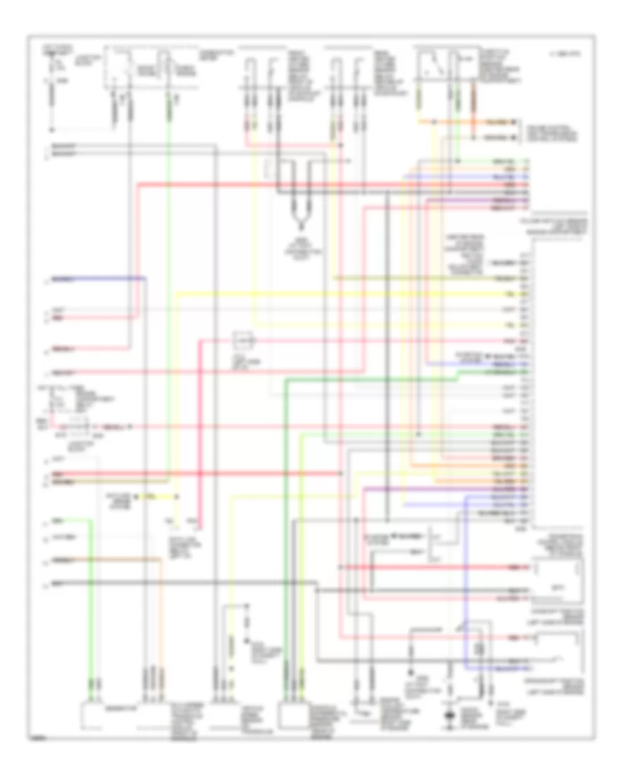
2.0L Turbo, Engine Performance Wiring Diagrams (1 of 2) for Mitsubishi Eclipse RS 1995

List of elements for 2.0L Turbo, Engine Performance Wiring Diagrams (1 of 2) for Mitsubishi Eclipse RS 1995:
- (front floor upper cross- member)
- (right side of safety wall)
- A/c system
- Acc
- B-53
- B-54
- C 1995 vftc
- Capacitor (rear of engine)
- Cooling fan system
- Egr solenoid valve (center of safety wall)
- Engine compartment relay box
- Engine speed detection connector (center rear of engine compartment)
- Evaporative emission purge solenoid valve (center of safety wall)
- Fl4 20a
- Fuel
- Fuel pressure solenoid valve (left side of safety wall)
- Fuel pump
- Fuel pump check connector (center rear of engine compartment)
- G123
- G300
- Headlight relay
- Hot at all times
- Idle air control motor (rear of engine)
- Idle up diode (behind center of i/p)
- Ignition coil
- Ignition switch
- Injectors
- Instrument cluster system (tachometer)
- Lock
- Mfi relay (behind right front of console)
- Nca
- Power steering pressure switch (right front of engine)
- Power transistor (center rear of engine)
- Powertrain control module (behind front of console)
- Red
- Resistor (left side of engine)
- Run
- Spark plugs
- Start
- Tacho
- Turbocharger waste gate solenoid valve (right front of engine)
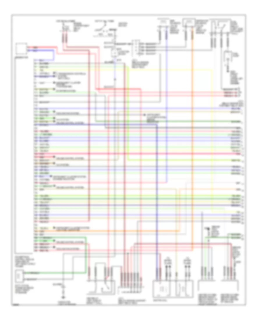
2.0L Turbo, Engine Performance Wiring Diagrams (2 of 2) for Mitsubishi Eclipse RS 1995
List of elements for 2.0L Turbo, Engine Performance Wiring Diagrams (2 of 2) for Mitsubishi Eclipse RS 1995:
- (at foot
- (center rear
- (right side of safety wall)
- A/t
- Antilock brake system
- B-50
- B-55
- B-56
- B-66
- B-75
- Boost gauge
- C 1995 vftc
- C-06
- Camshaft position sensor (left side of engine)
- Check engine
- Combination meter
- Compartment)
- Crankshaft position sensor (left side of engine)
- Cruise control and transmission control systems
- Data link connector (below left i/p)
- Distribution
- Distribution duct)
- Duct)
- Elc 4-speed automatic transaxle control module (front of console)
- Engine compartment relay box
- Engine coolant temperature sensor (right side of engine)
- F11 10a
- F8 10a
- Front heated oxygen sensor (below front of vehicle, on exhaust manifold)
- G123
- G123 (right side of safety wall)
- G206
- Generator
- Hot at all times
- Hot in run or start
- Ignition timing adjustment connector
- J/c 2 (left side of i/p)
- Junction block
- Knock sensor (rear of engine)
- M/t
- Manifold differential pressure sensor (rear of engine)
- Nca
- Of engine
- Pnk
- Powertrain control module (behind front of console)
- Rear heated oxygen sensor (below center of vehicle, on exhaust)
- Red
- Red/
- Starter system
- Starting system
- Throttle position sensor (center rear of engine compartment)
- Vehicle speed sensor (on transaxle)
- Volume air flow sensor (left side of engine compartment)
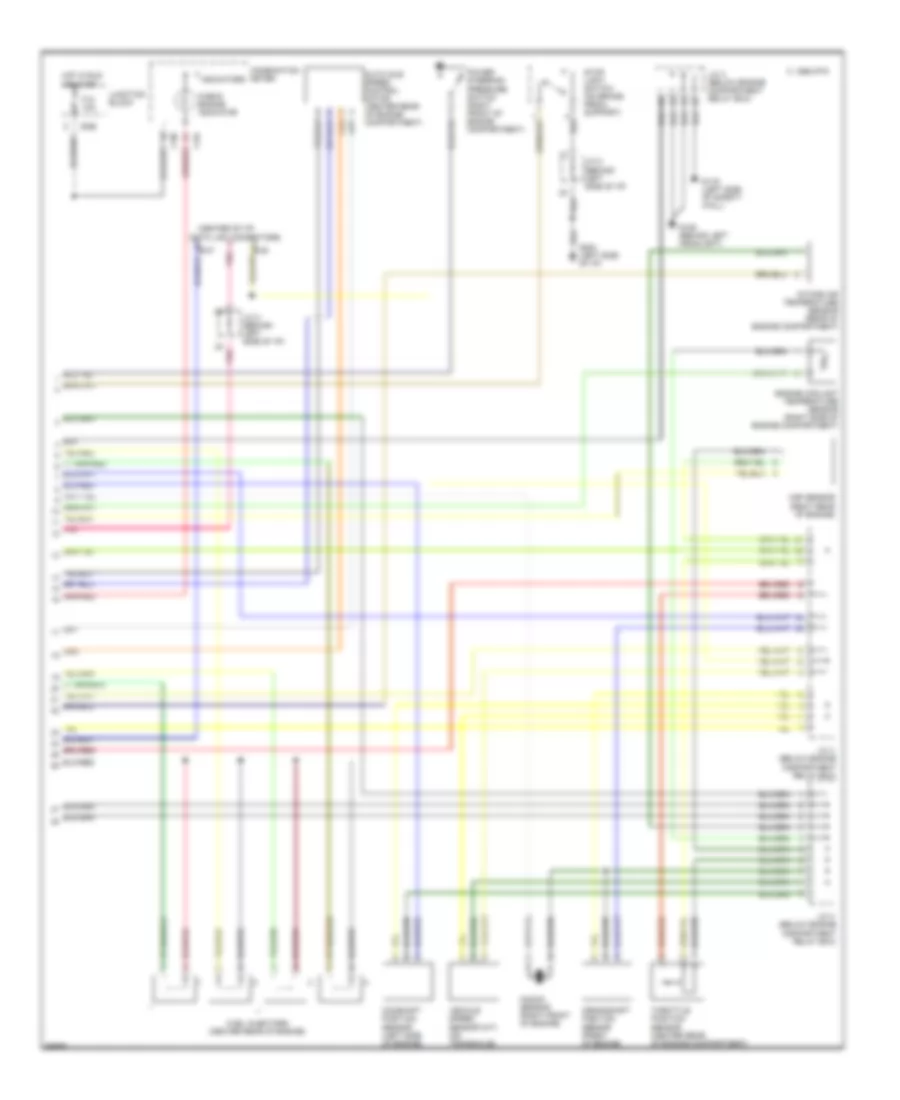
2.0L, Engine Performance Wiring Diagrams (1 of 2) for Mitsubishi Eclipse RS 1995
List of elements for 2.0L, Engine Performance Wiring Diagrams (1 of 2) for Mitsubishi Eclipse RS 1995:
- (behind foot distri- bution duct)
- A/c system
- Acc
- Asd relay (left side of safety wall)
- Aspirator solenoid valve (left front of engine)
- B-49
- B-75
- Capacitor (left of engine)
- Cooling fan system
- Cruise control system
- Duty cycle purge solenoid (right front of engine)
- Egr solenoid valve (right rear of engine)
- Engine compartment relay box
- Fl4 30a
- Fuel pump
- Fuel pump relay (left side of safety wall)
- G206
- G300 (front floor upper left cross- member)
- Generator
- Heated oxygen sensor (front) (below front of vehicle on ex- haust manifold)
- Heated oxygen sensor (rear) (below center of vehicle)
- Hot at all times
- Ignition coil
- Ignition switch
- Instrument cluster system (brake indicator)
- Instrument cluster system (charge indicator)
- Instrument cluster system (low fuel indicator)
- Instrument cluster system (tachometer)
- J/c 3 (below engine compart- ment relay box)
- J/c 3 (below engine compartment relay box)
- J/c 4 (below engine com- partment relay box)
- Junction block
- Lock
- Nca
- Pnk
- Powertrain control module (forward of left front strut tower)
- Red
- Run
- Start
- Starter system
- To spark plugs
- Transmission controls system (eatx ecu)
2.0L, Engine Performance Wiring Diagrams (2 of 2) for Mitsubishi Eclipse RS 1995
List of elements for 2.0L, Engine Performance Wiring Diagrams (2 of 2) for Mitsubishi Eclipse RS 1995:
- (center of i/p)
- Auto idle speed control motor (center rear of engine compartment)
- B-37
- B-38
- B-66
- C 1995 vftc
- C-04
- C-06
- Camshaft position sensor (left side of engine)
- Check engine indicator
- Combination meter
- Crankshaft position sensor (front of engine)
- Data link connectors
- Engine coolant temperature sensor (right side of engine compartment)
- F12 10a
- Fuel injectors (center rear of engine)
- G106 (behind left headlight)
- G116 (left side of safety wall)
- G202 (left side of i/p)
- Hot in run or start
- Indicators
- Intake air temperature sensor (rear of engine compartment)
- J/c 2 (behind left side of i/p)
- J/c 3 (below engine compartment relay box)
- J/c 4 (below engine compartment relay box)
- Junction block
- Knock sensor (right front of engine)
- Map sensor (right rear of engine)
- Pnk
- Power steering pressure switch (right front of engine compartment)
- Stop light switch (on brake pedal support)
- Throttle position sensor (center rear of engine compartment)
- Vehicle speed sensor (m/t) (on transaxle)