ENGINE PERFORMANCE
2.5L
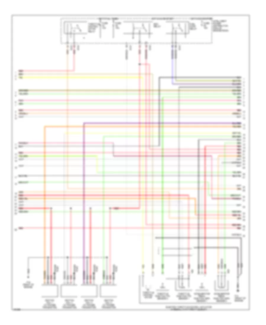
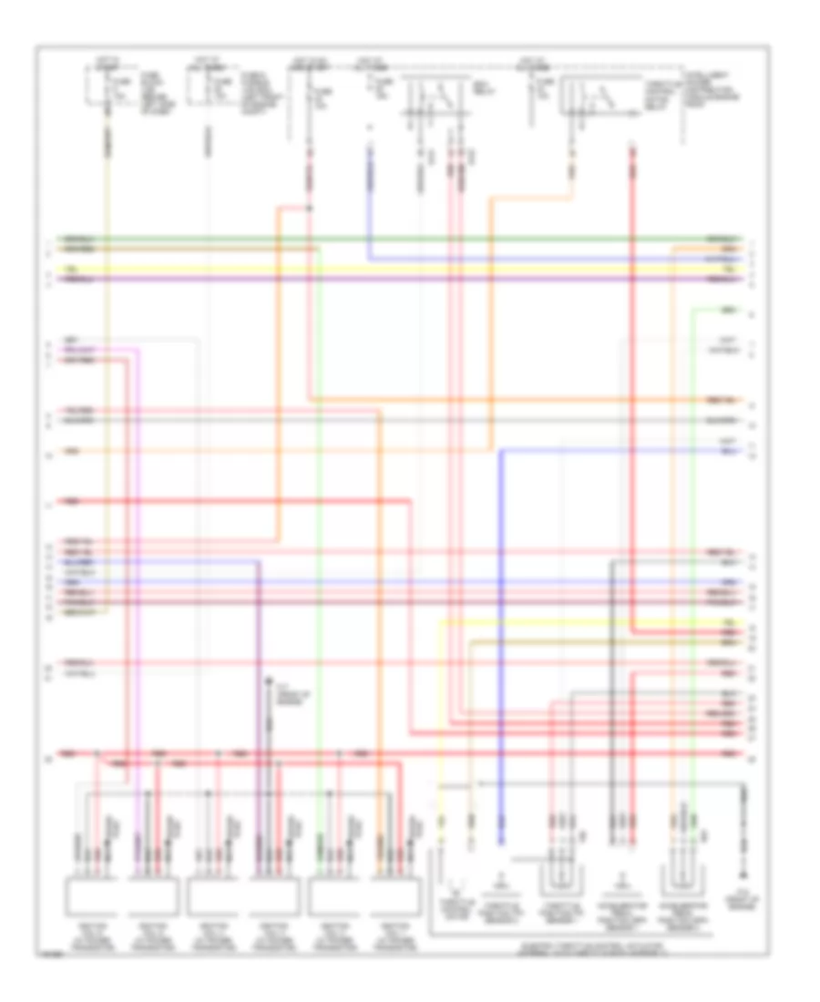
2.5L, Engine Performance Wiring Diagram (1 of 4) for Nissan Altima S 2004

List of elements for 2.5L, Engine Performance Wiring Diagram (1 of 4) for Nissan Altima S 2004:
- (front of engine) f16
- (left side of engine compt) e14
- 15p
- Af-h1
- Af-un1
- Af-vm1
- Afip1
- Avcc
- Avcc2
- Combination meter
- Computer data lines system
- Condenser 2 (right side of engine compt)
- Crankshaft position sensor (pos) (below starter motor)
- Engine control module (behind glove box)
- Evap
- Evap canister purge volume control solenoid valve (near throttle body)
- F14 (on front of engine)
- Ftrps
- Fuel injector
- Fuse 10a
- Fuse block (j/b) (behind left side of dash)
- Gnd
- Hot in on or start
- Inj 1
- Inj 2
- Inj 3
- Inj 4
- Inj 6
- Ivc
- Knk1
- Knock sensor (lower right side of cylinder block)
- Malfunction indicator lamp
- Motor1
- Motor2
- Nca
- Neutral
- O2hrr
- Park/ neutral position switch (left rear of transaxle)
- Pdpres
- Phase lh
- Pnk
- Pnk (or red)
- Pos
- Ps pres
- Qa+
- Red
- Refrigerant pressure sensor (right front of engine compt)
- Tps1
- Unified meter control unit
- V mot
- Vias
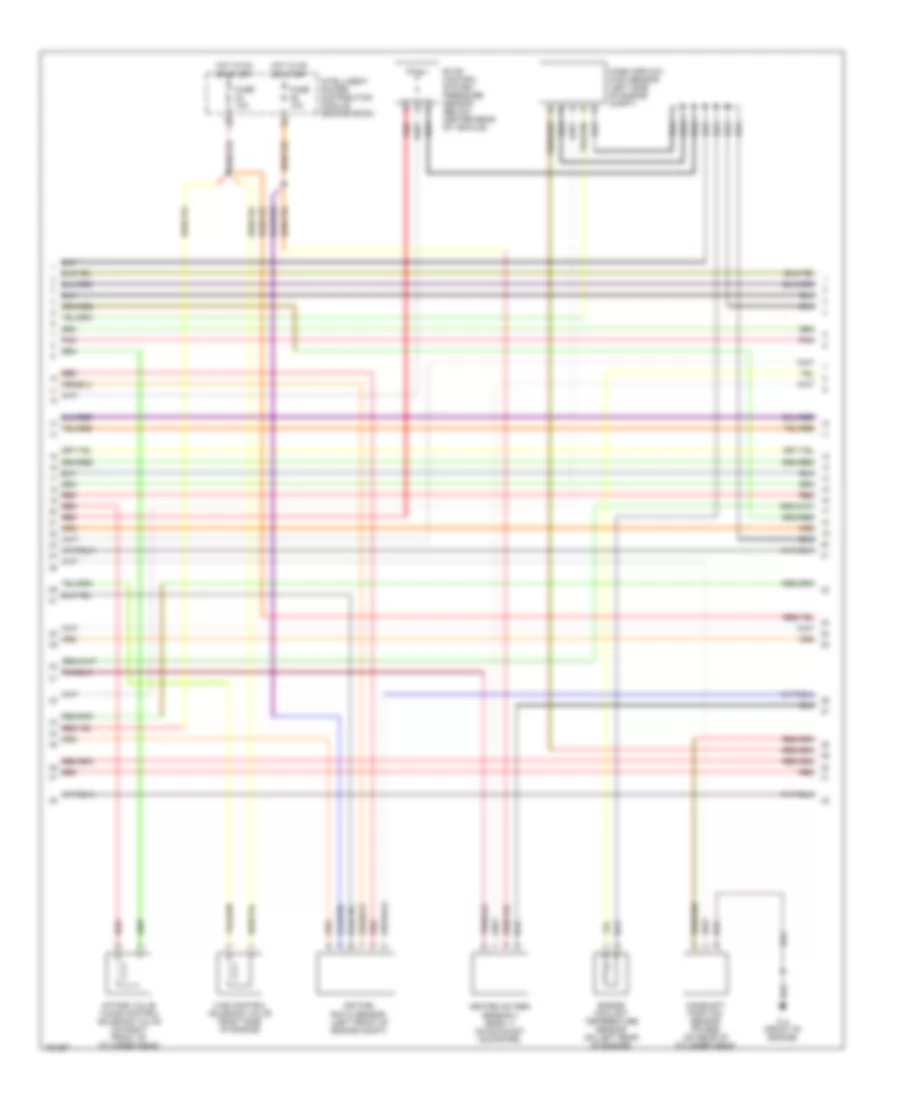
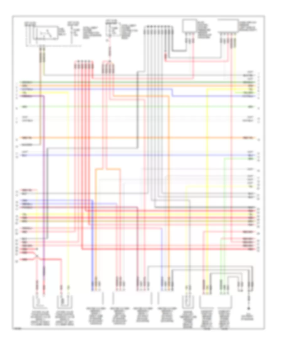
2.5L, Engine Performance Wiring Diagram (2 of 4) for Nissan Altima S 2004
List of elements for 2.5L, Engine Performance Wiring Diagram (2 of 4) for Nissan Altima S 2004:
- Accelerator pedal position (app) sensor 1
- Accelerator pedal position (app) sensor 2
- E121
- E122
- E124
- E40
- Ecm relay
- Electric throttle control actuator (integral with throttle body)
- F14 (front of engine)
- F16 (front of engine)
- F50
- Fuel pump relay
- Fuse 10a
- Fuse 15a
- Hot at all times
- Hot in on or start
- Ignition coil 1 (w/ power transistor)
- Ignition coil 2 (w/ power transistor)
- Ignition coil 3 (w/ power transistor)
- Ignition coil 4 (w/ power transistor)
- Intelligent power distribution module (engine room)
- Nca
- Plug spark
- Pnk
- Red
- Spark plug
- Throttle control motor
- Throttle control motor relay
- Throttle position (tp) sensor 1
- Throttle position (tp) sensor 2
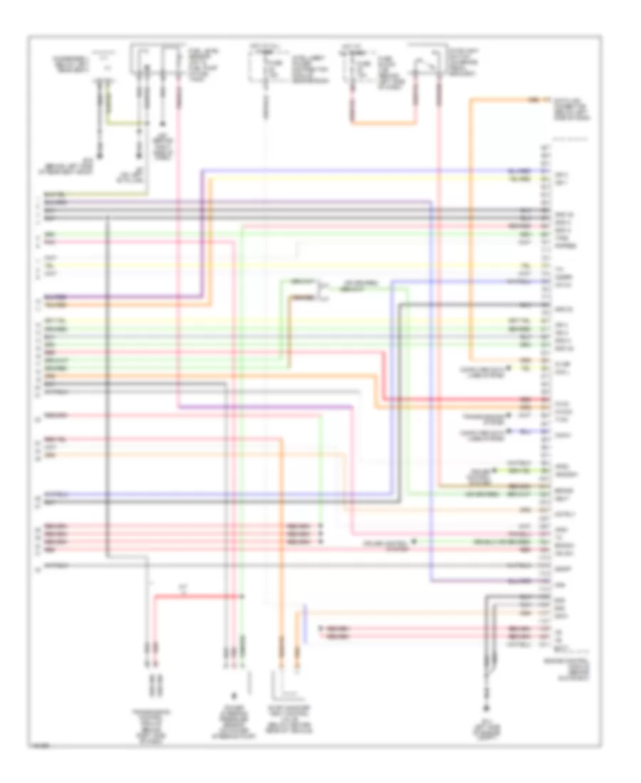
2.5L, Engine Performance Wiring Diagram (3 of 4) for Nissan Altima S 2004
List of elements for 2.5L, Engine Performance Wiring Diagram (3 of 4) for Nissan Altima S 2004:
- Air fuel ratio sensor (left front of engine compt)
- Camshaft position sensor (phase) (on rear of cylinder head)
- Engine coolant temperature sensor (on left rear of engine)
- Evap control system pressure sensor (below center rear of vehicle)
- F14 (front of engine)
- Fuse 10a
- Heated oxygen sensor 2 (bank 1) (on exhaust downpipe)
- Hot in on or start
- Intake valve timing control solenoid valve (on right front of cylinder head)
- Intelligent power distribution module (engine room)
- Mass airflow (maf) sensor (left side of engine compt)
- Pnk
- Red
- Vias control solenoid valve (right side of engine)
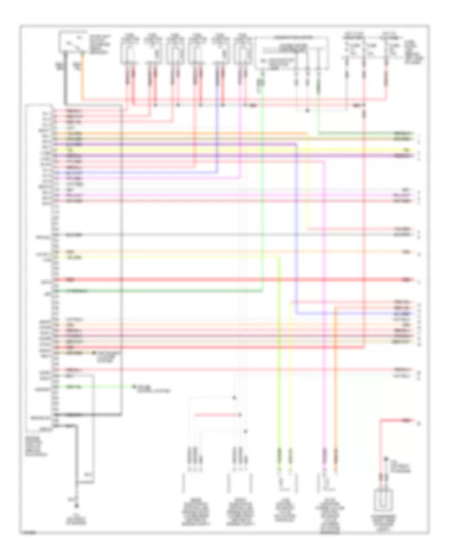
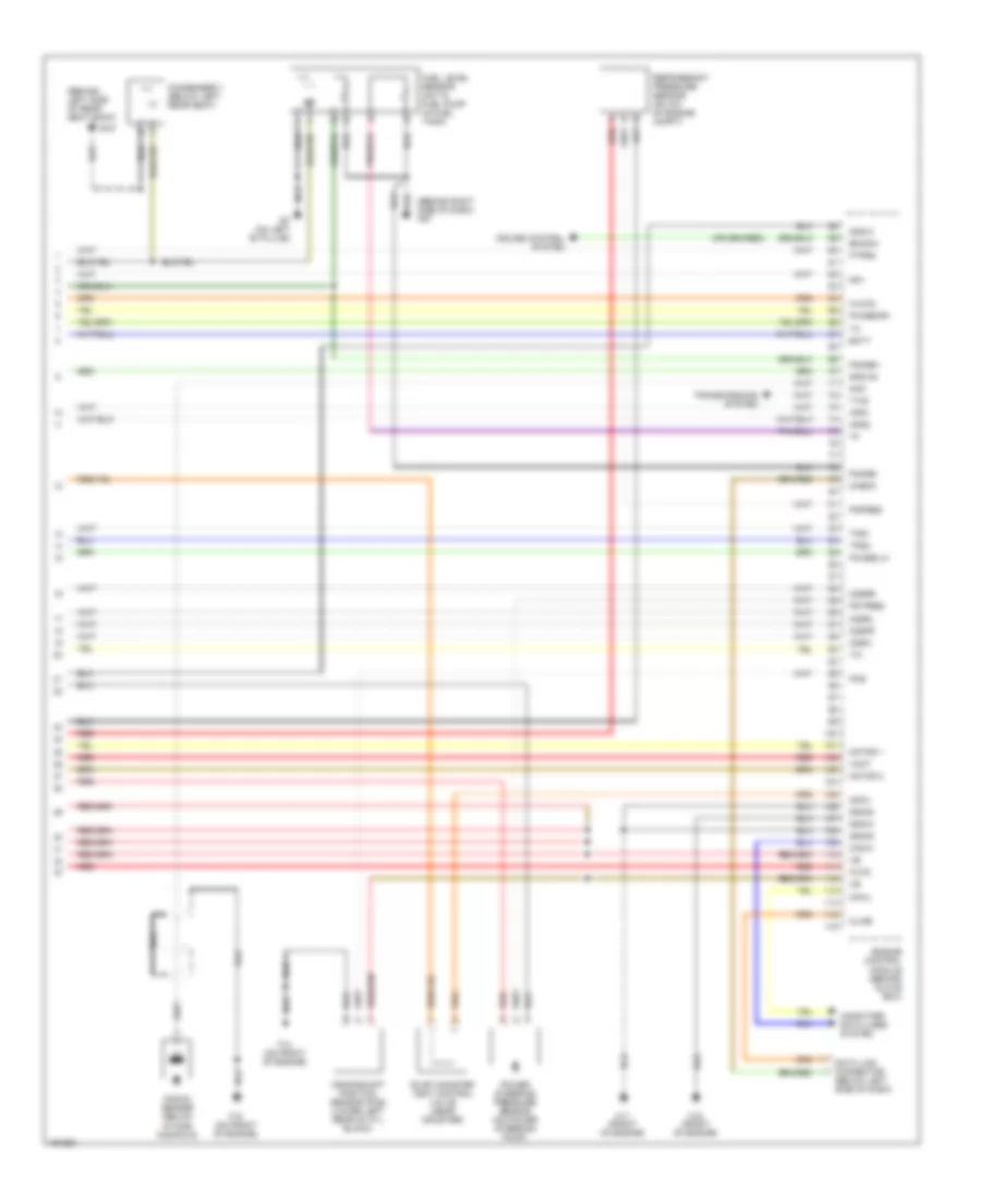
2.5L, Engine Performance Wiring Diagram (4 of 4) for Nissan Altima S 2004
List of elements for 2.5L, Engine Performance Wiring Diagram (4 of 4) for Nissan Altima S 2004:
- A/f-ia1
- A/t
- Aps1
- Aps2
- Ascdsw
- Avcc
- Avcc2
- B19 (behind left side of rear seat back)
- B7 (on left "b" pillar)
- Batt
- Bncsw
- Brake
- Can l
- Can-h
- Cdcv
- Computer data lines system
- Condenser 1 (below left rear seat)
- Cruise control system
- Data link connector (below left side of dash)
- E14 left side of engine compt)
- Engine control module (behind glove box)
- Evap canister vent control valve (below center rear of vehicle)
- Fpr
- Fuel level sensor unit & fuel pump (in fuel tank)
- Fuse 10a
- Fuse 15a
- Fuse block (j/b) (behind left side of dash)
- Gnd
- Gnd 02
- Gnd a
- Gnd a2
- Hot at all times
- Ign 1
- Ign 2
- Ign 3
- Ign 4
- Ign sw
- Intelligent power distribution module (engine room)
- Kline
- M57 (behind right side of dash)
- Motrly
- Neut
- O2srr
- Pdpres
- Pnk
- Power steering pressure sensor (on power steering pump)
- Red
- Sen gnd
- Ssoff
- Stoplight switch (on brake pedal bracket)
- Tps2
- Transmission control module (behind right side of dash)
- Transmissions system
- Tv00
3.5L
3.5L, Engine Performance Wiring Diagram (1 of 4) for Nissan Altima S 2004
List of elements for 3.5L, Engine Performance Wiring Diagram (1 of 4) for Nissan Altima S 2004:
- 15p
- Ascdsw
- Brake sw
- Combination meter
- Condenser 2 (right side of engine compt)
- Crtn
- Cruise control system
- Emnt1
- Emnt2
- Engine control module (behind glove box)
- Evap
- Evap canister purge volume control solenoid valve (on rear of intake manifold)
- F14 (on front of engine)
- F16 (on front of engine)
- Fpr sol
- Front electronic controlled engine mount (lower front center of engine compt)
- Fuel injector
- Fuse 10a
- Fuse block (j/b) (behind left side of dash)
- Gnd-c
- Hot at all times
- Hot in on or start
- Ign 1
- Ign 2
- Ign 3
- Ign 4
- Ign 5
- Ign 6
- Ignsw
- Inj 1
- Inj 2
- Inj 3
- Inj 4
- Inj 5
- Inj 6
- Instrument cluster system
- Ivcb1
- Ivcb2
- Led
- Malfunction indicator lamp
- Motrly
- Neut
- O2hfl
- O2hfr
- O2hrl
- O2hrr
- Rear electronic controlled engine mount (lower rear center of engine compt)
- Red
- Ssoff
- Stoplight switch (on brake pedal bracket)
- Stsw
- Unified meter control unit
- Vias
- Vias control solenoid valve (on intake manifold)
3.5L, Engine Performance Wiring Diagram (2 of 4) for Nissan Altima S 2004
List of elements for 3.5L, Engine Performance Wiring Diagram (2 of 4) for Nissan Altima S 2004:
- Accelerator pedal position (app) sensor 1
- Accelerator pedal position (app) sensor 2
- E121
- E122
- E40
- Ecm relay
- Electric throttle control actuator (integral with throttle body assembly)
- F15 (front of engine)
- F17 (front of engine)
- F50
- Fuse & fusible link box (left front of engine compt)
- Fuse 10a
- Fuse 15a
- Fuse block (j/b) (behind left side of dash)
- Hot at all times
- Hot in on and start
- Hot in start
- Ignition coil 1 (w/ power transistor)
- Ignition coil 2 (w/ power transistor)
- Ignition coil 3 (w/ power transistor)
- Ignition coil 4 (w/ power transistor)
- Ignition coil 5 (w/ power transistor)
- Ignition coil 6 (w/ power transistor)
- Intelligent power distribution module engine room
- Nca
- Plug spark
- Red
- Spark plug
- Throttle control motor
- Throttle control motor relay
- Throttle position (tp) sensor 1
- Throttle position (tp) sensor 2
3.5L, Engine Performance Wiring Diagram (3 of 4) for Nissan Altima S 2004
List of elements for 3.5L, Engine Performance Wiring Diagram (3 of 4) for Nissan Altima S 2004:
- Camshaft position sensor (phase) (bank 1) (rear of right cyl head)
- Camshaft position sensor (phase) (bank 2) (rear of left cyl head)
- Engine coolant temperature sensor (upper rear of engine)
- Evap control system pressure sensor (near evap canister)
- F14 (on front of engine)
- Fuel pump relay
- Fuse 10a
- Fuse 15a
- Heated oxygen sensor 1 (bank 1) (right side of engine, on exhaust manifold)
- Heated oxygen sensor 1 (bank 2) (left side of engine, on exhaust manifold)
- Heated oxygen sensor 2 (bank 1) (on right exhaust downpipe)
- Heated oxygen sensor 2 (bank 2) (on right exhaust downpipe)
- Hot in on or start
- Intake valve timing control solenoid valve (bank 1) (front of right cylinder head)
- Intake valve timing control solenoid valve (bank 2) (front of left cylinder head)
- Intelligent power distribution module engine room
- Mass airflow sensor (left side of engine compt)
- Red
3.5L, Engine Performance Wiring Diagram (4 of 4) for Nissan Altima S 2004
List of elements for 3.5L, Engine Performance Wiring Diagram (4 of 4) for Nissan Altima S 2004:
- (behind left side of rear seat back)
- (behind right side of dash) m57
- Aps1
- Aps2
- Avcc
- Avcc2
- B19
- B7 (on left "b" pillar)
- Batt
- Bncsw
- Can-h
- Can-l
- Cdcv
- Check
- Computer data lines system
- Condenser 1 (below left rear seat)
- Crankshaft position sensor (pos) (lower left rear of cyl block)
- Cruise control system
- Data link connector (below left side of dash)
- Engine control module (behind glove box)
- Evap canister vent control valve (near canister)
- F14 (on front of engine)
- F15 (on front of engine)
- F16 (front of engine)
- F17 (front of engine)
- Fgage+
- Fgage-
- Ftprs
- Fuel level sensor unit & fuel pump (in fuel tank)
- Gnd-a
- Gnd-a2
- Gnd-e
- Gnd-m
- Kline
- Knk
- Knock sensor (below intake manifold)
- Motor 1
- Motor 2
- Nca
- O2sfl
- O2sfr
- O2srl
- O2srr
- Pdpres
- Phase-lh
- Phase-rh
- Pos
- Power steering pressure sensor (on power steering pump)
- Ps pres
- Qa+
- Red
- Refrigerant pressure sensor (on a/c of engine compt)
- Tps1
- Tps2
- Transmissions system
- Tv00
- Vmot