ENGINE PERFORMANCE
2.5L
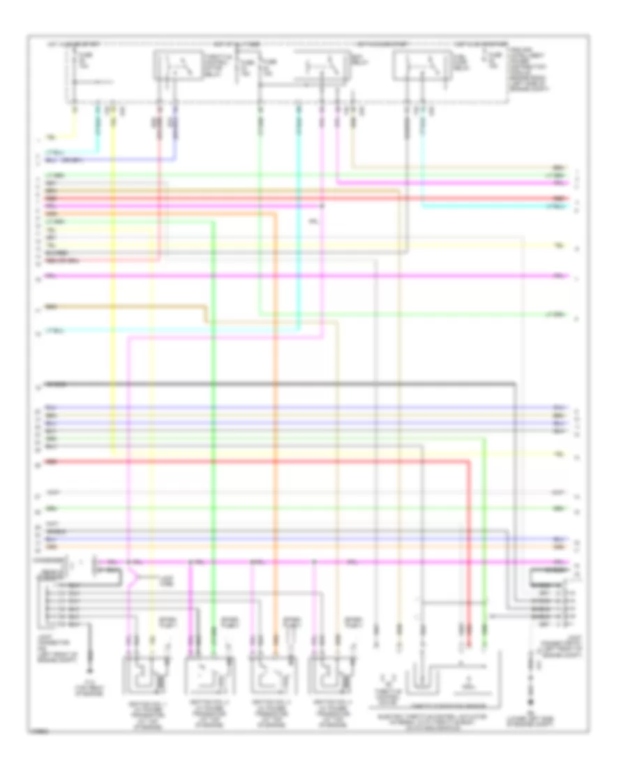
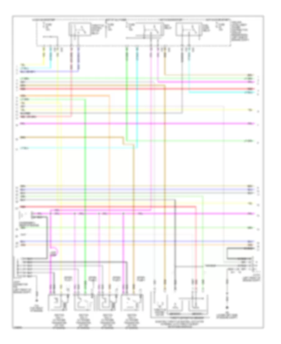
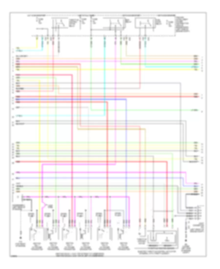
2.5L, Engine Performance Wiring Diagram, California (1 of 4) for Nissan Altima S 2012

List of elements for 2.5L, Engine Performance Wiring Diagram, California (1 of 4) for Nissan Altima S 2012:
- (behind left end of dash)
- 12m
- 3rdo2h
- 3rdo2s
- Af+1
- Af-1
- Afh1
- Avcc1
- Avcc1-cursen
- Avcc1-pspres
- Avcc1-tps-b1
- Avcc2
- Battery current sensor (left front of engine compt)
- Combination meter
- Computer data lines system
- Cursen
- E11
- E18
- E44
- E9 (lower left side of engine compt)
- Ecm (left front of engine compt)
- Engine coolant temperature sensor (left rear of engine)
- Evap
- Evap canister purge volume control solenoid valve (on intake manifold, near throttle body)
- F1 e3
- F90
- F91
- Fpr
- Fuel injectors (top of engine)
- Fuse 10a
- Fuse block (j/b)
- Gnd
- Gnda-cursen
- Gnda-o2sr2
- Gnda-pdres
- Gnda-pspres
- Gnda-ta1
- Gnda-tps-b1
- Gnda-tw
- Hot in on or start
- Ign 1
- Ign 2
- Ign 3
- Ign 4
- Inj 1
- Inj 2
- Inj 3
- Inj 4
- Ipdm e/r (intelligent power distribution e201
- Joint connector f04 (left front of engine compt)
- Joint connector f06 (left front of engine compt)
- Joint connector f07 (left side of engine compt)
- Junction block
- Malfunction indicator lamp
- Module engine room) (left side of engine compt)
- Motor1-b1
- Motor2-b1
- Motrly-b1
- O2hr1
- Osr1
- Output
- Pdpres
- Pnk
- Power steering pressure sensor (on power steering pump)
- Pspres
- Red
- Refrigerant pressure sensor (left front of engine compt)
- Scv1
- Scv2
- Scvpos
- Shield
- Sig
- Ssof
- Ta1
- Tps1-b1
- Tps2-b1
- Tumble control valve actuator (engine)
- Tumble control valve motor
- Tumble control valve position sensor
- Unified meter (w/ information display)
- Vmot-b1
- Vscv
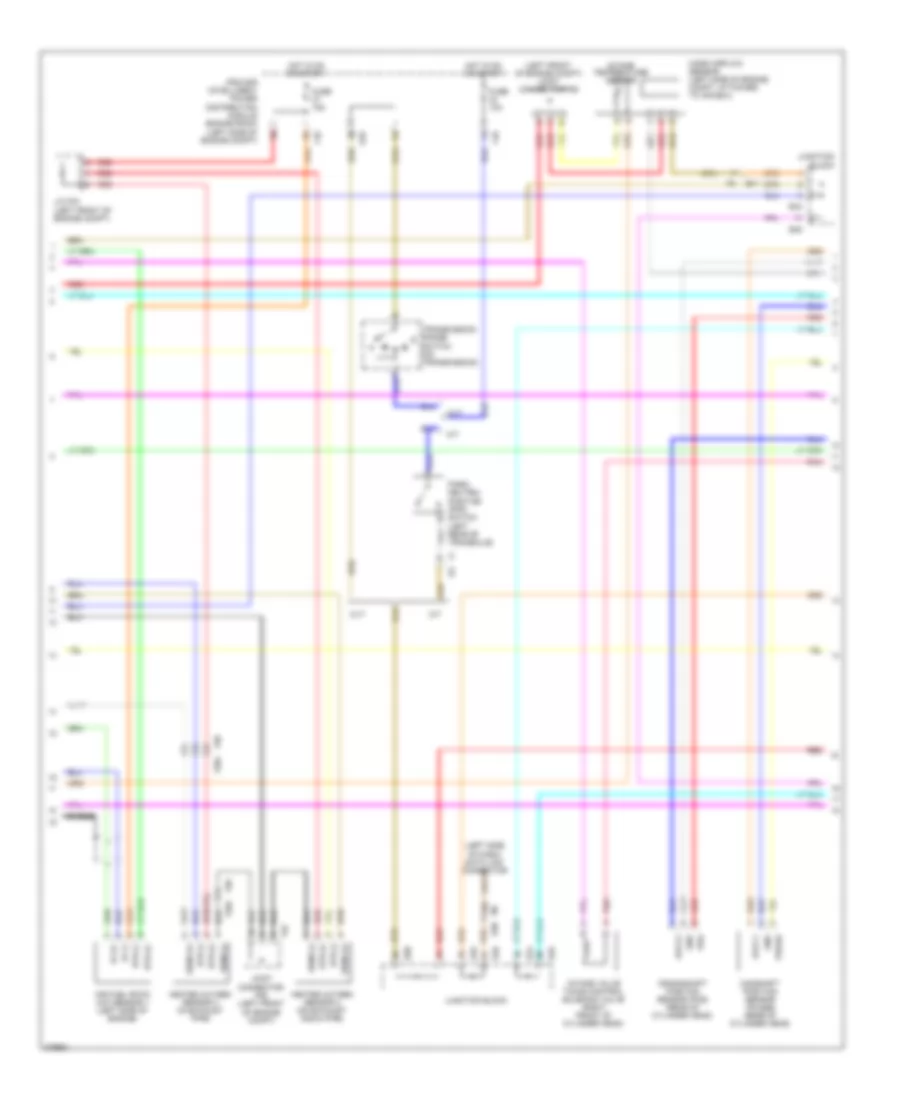
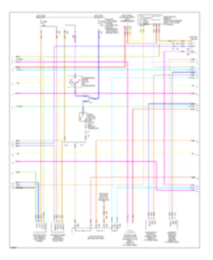
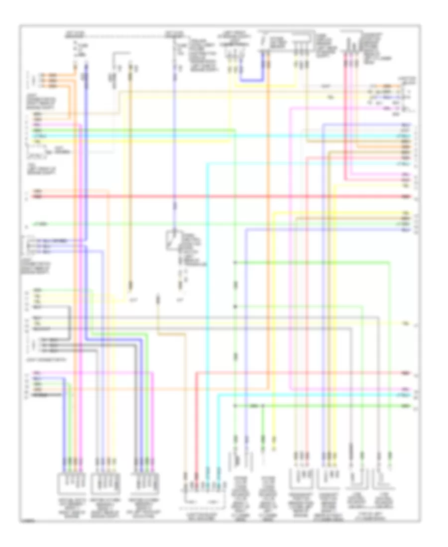
2.5L, Engine Performance Wiring Diagram, California (2 of 4) for Nissan Altima S 2012
List of elements for 2.5L, Engine Performance Wiring Diagram, California (2 of 4) for Nissan Altima S 2012:
- Condenser (rear of of engine)
- E11
- E18
- E9 (lower left side of engine compt)
- Ecm relay
- Electric throttle control actuator (integral with throttle body, on intake manifold)
- F10
- F15 (top front of engine)
- Fuel pump relay
- Fuse 10a
- Fuse 15a
- Hot at all times
- Hot in on or start
- Ignition coil 1 (w/ power transistor) (at top of engine)
- Ignition coil 2 (w/ power transistor) (at top of engine)
- Ignition coil 3 (w/ power transistor) (at top of engine)
- Ignition coil 4 (w/ power transistor) (at top of engine)
- Ipdm e/r (intelligent power distribution module engine room) (left side of engine compt)
- Joint connector f01 (left front of engine compt)
- Joint connector f05 (left front of engine compt)
- Loop wire
- Red
- Shield
- Spark plug 1
- Spark plug 2
- Spark plug 3
- Spark plug 4
- Throttle control motor
- Throttle control motor relay
- Throttle position sensor
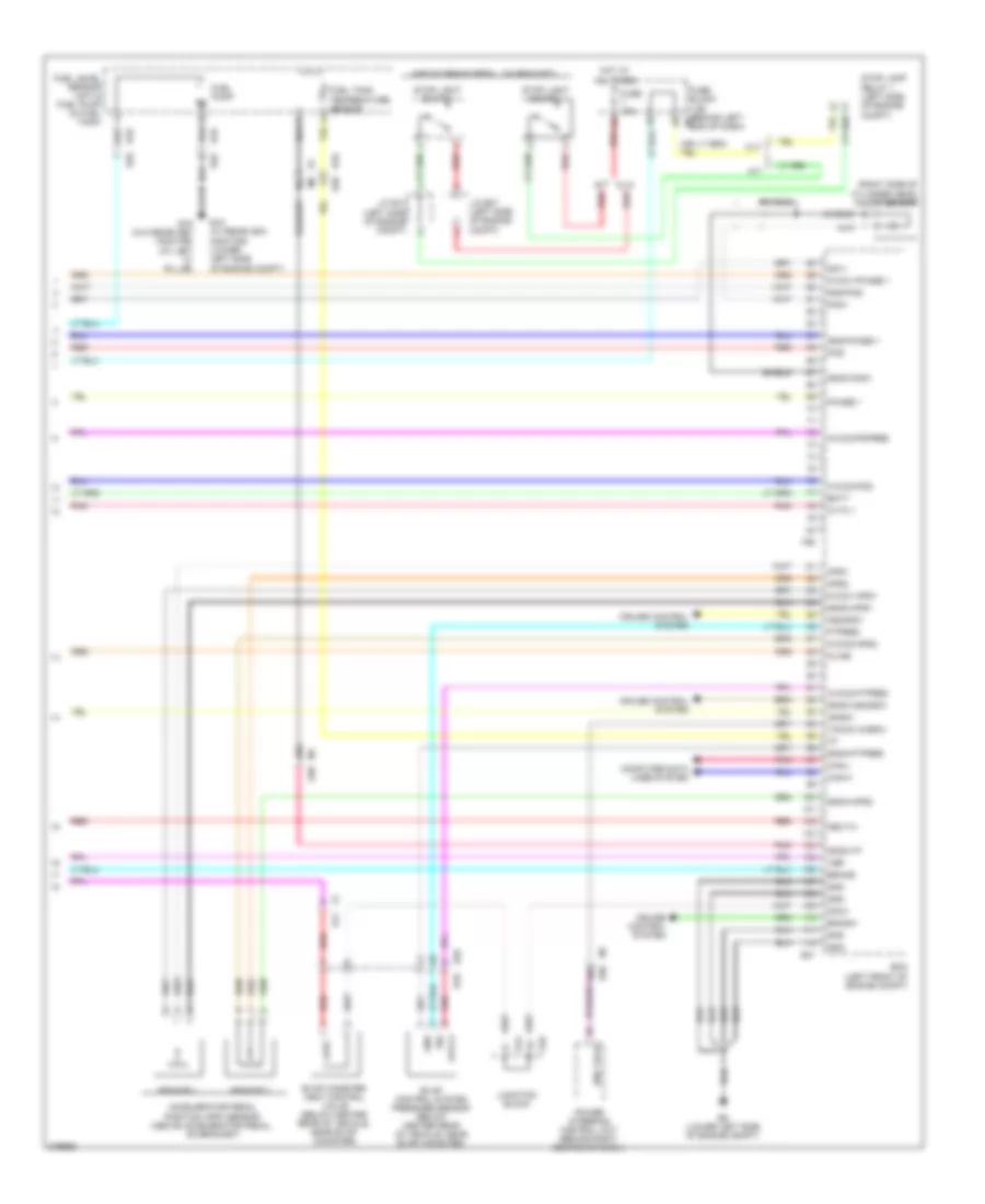
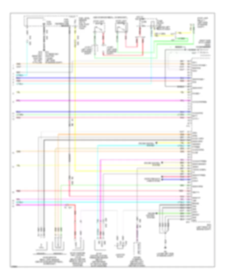
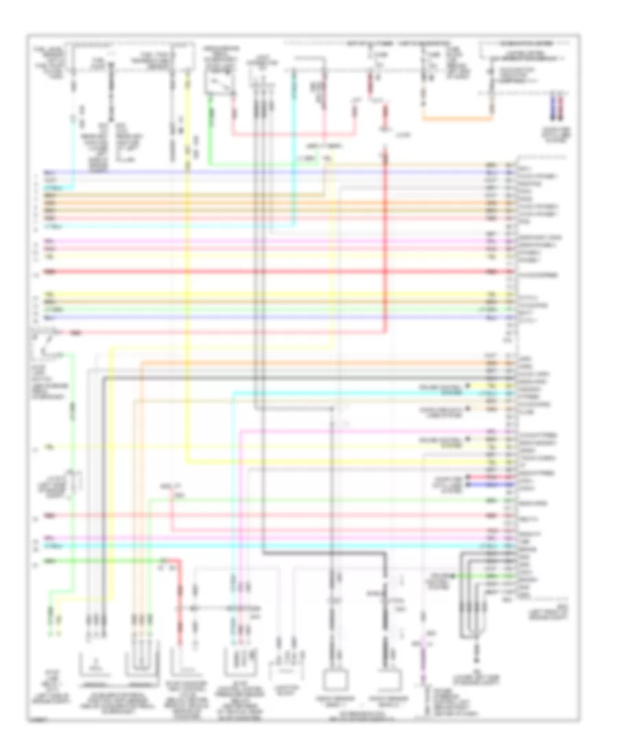
2.5L, Engine Performance Wiring Diagram, California (3 of 4) for Nissan Altima S 2012
List of elements for 2.5L, Engine Performance Wiring Diagram, California (3 of 4) for Nissan Altima S 2012:
- (left front of engine compt) joint connector f06
- (left side of dash) data link connector
- 34g
- Af (+)
- Af (-)
- Air fuel ratio (a/f) sensor 1 (left side of engine)
- Avcc1
- Avcc2
- Camshaft position sensor (phase) (rear of cylinder head)
- Crankshaft position sensor (pos) (rear of cylinder head)
- Cvt
- E11
- E18
- E44
- E45
- E46
- E50
- F1 e3
- F10
- F52
- F58 f204
- Fuse 10a
- Fuse 15a
- Gnd
- Heated oxygen sensor 2 (on exhaust down pipe)
- Heated oxygen sensor 3 (in exhaust pipe)
- Hot in on or start
- Htr (+)
- Htr (-)
- Intake temperature sensor
- Intake valve timing control solenoid valve (right front of cylinder head)
- Ipdm e/r (intelligent power distribution module engine room) (left side of engine compt)
- J/c f04 (left front of engine compt)
- Joint connector f06 (left front of engine compt)
- Junction block
- M/t
- M1 e30
- Mass airflow sensor (left side of engine compt, attached to air box)
- Park/ neutral position (pnp) switch (left rear of transaxle)
- Phase
- Pnk
- Pos
- Red
- Sens (+)
- Sens (-)
- Shield
- Transmission range switch (on transmission)
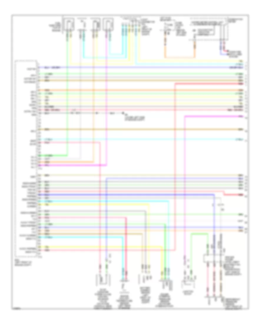
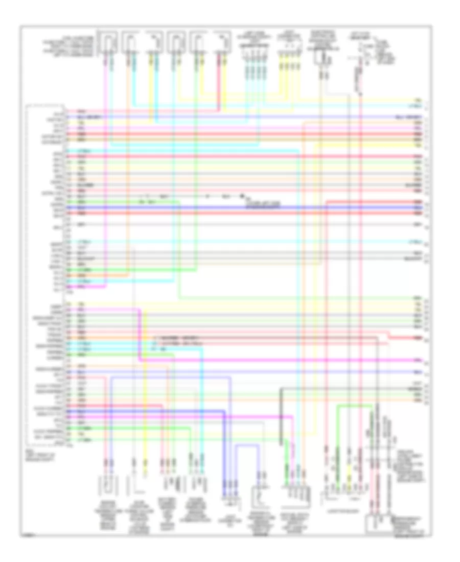
2.5L, Engine Performance Wiring Diagram, California (4 of 4) for Nissan Altima S 2012
List of elements for 2.5L, Engine Performance Wiring Diagram, California (4 of 4) for Nissan Altima S 2012:
- (above brake pedal, on bracket)
- (right side of cylinder head) knock sensor
- 30j
- 60g
- 63g
- Accelerator pedal position (app) sensor (above accelerator pedal, on bracket)
- Aps1
- Aps2
- Ascdsw
- Avcc1-aps1
- Avcc1-phase 1
- Avcc2
- Avcc2-aps2
- Avcc2-ftpres
- Avcc2-pdpres
- Avcc2-pos
- B1 m6
- B10
- B10 e29
- B19 (w/o rearview monitor) (at left "c" pillar)
- Batt
- Bncsw
- Brake
- Can-h
- Can-l
- Cdcv
- Computer data lines system
- Cruise control system
- Cvt
- Cvtc 1
- E15 (w/ rearview monitor) (lower left side of engine compt)
- E29
- E29 b10
- E31
- E44
- E45
- E9 (lower left side of engine compt)
- Ecm (left front of engine compt)
- Eng tach
- Evap canister vent control valve (below center rear of vehicle, near evap canister)
- Evap control system pressure sensor (below center rear of vehicle, near evap canister)
- F2 e11
- F90
- Ftpres
- Fuel level sensor unit & fuel pump (in fuel tank)
- Fuel pump
- Fuel tank temperature sensor
- Fuse 10a
- Fuse block (j/b) (behind left e6 end of dash)
- Gnd
- Gnd-phase 1
- Gnd-pos
- Gnda-aps1
- Gnda-aps2
- Gnda-ascdsw
- Gnda-ftpres
- Gnda-knk1
- Gnda-tf
- Hot at all times
- Ignsw
- J/c e07 (left side of engine compt)
- J/c e14 (left side of engine compt)
- Junction block
- Kline
- Knk1
- M/t
- M1 e30
- Neut-h
- Phase 1
- Pnk
- Pos
- Power steering control unit (behind right center of dash)
- Qa1+
- Red
- Sensor 1
- Sensor 2
- Shield
- Sig
- Stop lamp relay 1 (left side of engine compt)
- Stop light switch
- Tacho (cabin)
- Vbr
2.5L, Engine Performance Wiring Diagram, Except California (1 of 4) for Nissan Altima S 2012
List of elements for 2.5L, Engine Performance Wiring Diagram, Except California (1 of 4) for Nissan Altima S 2012:
- (or red)
- 12m
- Af+1
- Af-1
- Afh1
- Avcc1
- Avcc1-cursen
- Avcc1-pspres
- Avcc1-tps-b1
- Battery current sensor (left front of engine compt)
- Combination meter
- Computer data lines system
- Cursen
- E11
- E18
- E44
- E45
- E9 (lower left side of engine compt)
- Ecm (left front of engine compt)
- Engine coolant temperature sensor (left rear of engine)
- Evap
- Evap canister purge volume control solenoid valve (on intake manifold, near throttle body)
- F13
- F14
- Fpr
- Fuel injectors (top of engine)
- Fuse 10a
- Fuse block (j/b) (behind left end of dash)
- Gnd
- Gnda-cursen
- Gnda-o2sr2
- Gnda-pdres
- Gnda-pspres
- Gnda-ta1
- Gnda-tps-b1
- Gnda-tw
- Hot in on or start
- Ign 1
- Ign 2
- Ign 3
- Ign 4
- Inj 1
- Inj 2
- Inj 3
- Inj 4
- Ipdm e/r power (intelligent distribution e201
- Joint connector f04 (left front of engine compt)
- Junction block
- Malfunction indicator lamp (mil)
- Module engine room) (left side of engine compt)
- Motor1-b1
- Motor2-b1
- Motrly-b1
- O2hr1
- Osr1
- Output
- Pdpres
- Pnk
- Power steering pressure sensor (on power steering pump)
- Pspres
- Red
- Refrigerant pressure sensor (left front of engine compt)
- Sig
- Ssof
- Ta1
- Tps1-b1
- Tps2-b1
- Unified meter control unit w/ information display
- Vmot-b1
2.5L, Engine Performance Wiring Diagram, Except California (2 of 4) for Nissan Altima S 2012
List of elements for 2.5L, Engine Performance Wiring Diagram, Except California (2 of 4) for Nissan Altima S 2012:
- Condenser 2 (rear of engine)
- E11
- E18
- E9 (lower left side of engine compt)
- Ecm relay
- Electric throttle control actuator (integral with throttle body, on intake manifold)
- F10
- F15 (top front of engine)
- Fuel pump relay
- Fuse 10a
- Fuse 15a
- Hot at all times
- Hot in on or start
- Ignition coil 1 (w/ power transistor) (at top of engine)
- Ignition coil 2 (w/ power transistor) (at top of engine)
- Ignition coil 3 (w/ power transistor) (at top of engine)
- Ignition coil 4 (w/ power transistor) (at top of engine)
- Ipdm e/r (intelligent power distribution module engine room) (left side of engine compt)
- J/c f01 (left front of engine compt)
- Joint connector f05 (left front of engine compt)
- Loop wire
- Red
- Sensor 1
- Sensor 2
- Shield
- Spark plug 1
- Spark plug 2
- Spark plug 3
- Spark plug 4
- Throttle control motor
- Throttle control motor relay
- Throttle position sensor
2.5L, Engine Performance Wiring Diagram, Except California (3 of 4) for Nissan Altima S 2012
List of elements for 2.5L, Engine Performance Wiring Diagram, Except California (3 of 4) for Nissan Altima S 2012:
- (left front of engine compt) joint connector f06
- (left side of dash) data link connector
- 34c
- Af (+)
- Af (-)
- Air fuel ratio (a/f) sensor 1 (left side of engine)
- Avcc1
- Avcc2
- Camshaft position sensor (phase) (rear of cylinder head)
- Crankshaft position sensor (pos) (rear of cylinder head)
- Cvt
- E18
- E30
- E44
- E45
- E46
- E50
- F10
- Fuse 10a
- Fuse 15a
- Gnd
- Heated oxygen sensor 2 (on exhaust down pipe)
- Hot in on or start
- Htr (+)
- Htr (-)
- Intake air temp sens
- Intake valve timing control solenoid valve (right front of cylinder head)
- Ipdm e/r (intelligent power distribution module engine room) (left side of engine compt)
- Junction block
- Junction block e50, e45, e44 & e46
- M/t
- Mass airflow sensor (left side of engine compt, attached to air box)
- Park/ neutral position (pnp) switch (left rear of transaxle)
- Pnk
- Pos
- Red
- Shield
- Snsr (+)
- Snsr (-)
- Transmission range switch (on transmission)
2.5L, Engine Performance Wiring Diagram, Except California (4 of 4) for Nissan Altima S 2012
List of elements for 2.5L, Engine Performance Wiring Diagram, Except California (4 of 4) for Nissan Altima S 2012:
- (above brake pedal, on bracket)
- (right side of cylinder head) knock sensor
- 30j
- 60g
- 63g
- Accelerator pedal (app) sensor (above accelerator pedal, on bracket)
- Aps1
- Aps2
- Ascdsw
- Avcc1-aps1
- Avcc1-phase 1
- Avcc2
- Avcc2-aps2
- Avcc2-ftpres
- Avcc2-pdpres
- Avcc2-pos
- B10
- B19 (w/o rearview monitor) (at left "c" pillar)
- Batt
- Bncsw
- Brake
- Can-h
- Can-l
- Cdcv
- Computer data lines system
- Cruise control system
- Cvt
- Cvtc 1
- E10
- E11
- E15 (w/ rearview monitor) (lower left side of engine compt)
- E29
- E30
- E44
- E45
- E9 (lower left side of engine compt)
- Ecm (left front of engine compt)
- Eng tacho
- Evap canister vent control valve (below center rear of vehicle, near evap canister)
- Evap control system pressure sensor (below center rear of vehicle, near evap canister)
- F13
- Ftpres
- Fuel level sensor unit & fuel pump (in fuel tank)
- Fuel pump
- Fuel tank temperature sensor
- Fuse 10a
- Fuse block (j/b) (behind left e6 end of dash)
- Gnd
- Gnd-phase 1
- Gnd-pos
- Gnda-aps1
- Gnda-aps2
- Gnda-ascdsw
- Gnda-ftpres
- Gnda-knk1
- Gnda-tf
- Hot at all times
- Ignsw
- J/c e07 (left side of engine compt)
- J/c e14 (left side of engine compt)
- Junction block
- Kline
- Knk1
- M/t
- Neut-h
- Phase 1
- Pnk
- Pos
- Power steering control unit (behind right center of dash)
- Qa1+
- Red
- Sensor 1
- Sensor 2
- Shield
- Sig
- Stop lamp relay 1 (left side of engine compt)
- Stop light switch
- Tacho (cabin)
- Vbr
3.5L
3.5L, Engine Performance Wiring Diagram (1 of 4) for Nissan Altima S 2012
List of elements for 3.5L, Engine Performance Wiring Diagram (1 of 4) for Nissan Altima S 2012:
- (left side of engine compt) joint connector f07
- Af (+)
- Af (-)
- Af+1
- Af+2
- Af-1
- Af-2
- Afh1
- Afh2
- Air fuel ratio (a/f) sensor 1 (bank 2) (left side of engine)
- Avcc1
- Avcc1-cursen
- Avcc1-pspres
- Avcc1-tps-b1
- Avcc2
- Battery current sensor (left side of engine compt)
- Cursen
- E11
- E18
- E44
- E45
- E46
- E9 (lower left side of engine compt)
- Ecm (left front of engine compt)
- Electronic controlled engine mount control solenoid valve
- Emmnv
- Engine coolant temperature sensor (upper rear of engine)
- Engine oil temperature sensor (lower right front of engine)
- Enmn1
- Evap
- Evap canister purge volume control solenoid valve (top rear of engine)
- F78
- F79
- Fpr
- Fuel injectors (injectors 1, 3 & 5: top of right cylinder bank) (injectors 2, 4 & 6: top of left cylinder bank)
- Fuse 10a
- Fuse block (j/b) (behind left end of dash)
- Gnd
- Gnda-cursen
- Gnda-o2sr1 & 2
- Gnda-pdpres
- Gnda-pspres
- Gnda-tps-b1
- Gnda-tw to1
- Hot in on or start
- Htr (+)
- Htr (-)
- Ign
- Ign 1
- Ign 2
- Ign 3
- Ign 4
- Ign 5
- Ign 6
- Inj 1
- Inj 2
- Inj 3
- Inj 4
- Inj 5
- Inj 6
- Ipdm e/r (intelligent power distribution e201
- Joint connector f01
- Joint connector f08
- Junction block
- Module engine room) (left side of engine compt)
- Motor1-b1
- Motor2-b1
- Motrly-b1
- O2hr1
- O2hr2
- O2sr1
- O2sr2
- Output
- Pdpres
- Pnk
- Power steering pressure sensor (on power steering pump)
- Pspres
- Qa1, gnda-ta1
- Red
- Refrigerant pressure sensor (left front of engine compt)
- Shield
- Sig
- Signal
- Ssoff
- Ta1
- To1
- Tps1-b1
- Tps2-b1
- Vias 1
- Vias 2
- Vmot-b1
3.5L, Engine Performance Wiring Diagram (2 of 4) for Nissan Altima S 2012
List of elements for 3.5L, Engine Performance Wiring Diagram (2 of 4) for Nissan Altima S 2012:
- (ignition coils 1, 3 & 5: top of right cylinder bank) (ignition coils 2, 4 & 6: top of left cylinder bank)
- (integral with throttle body)
- Condenser 2 (left rear of of engine)
- E11
- E18
- E9 (lower left side of engine compt)
- Ecm relay
- Electric throttle control actuator
- F10
- F15 (top front of engine)
- Fuel pump relay
- Fuse 10a
- Fuse 15a
- Hot at all times
- Hot in on or start
- Ignition coil 1 (w/ power transistor)
- Ignition coil 2 (w/ power transistor)
- Ignition coil 3 (w/ power transistor)
- Ignition coil 4 (w/ power transistor)
- Ignition coil 5 (w/ power transistor)
- Ignition coil 6 (w/ power transistor)
- Ipdm e/r (intelligent power distribution module engine room) (left side of engine compt)
- Joint connector f04 (left front of engine compt)
- Loop wire
- Pnk
- Red
- Sensor 1
- Sensor 2
- Shield
- Spark plug 1
- Spark plug 2
- Spark plug 3
- Spark plug 4
- Spark plug 5
- Spark plug 6
- Throttle control motor
- Throttle control motor relay
- Throttle position sensor
3.5L, Engine Performance Wiring Diagram (3 of 4) for Nissan Altima S 2012
List of elements for 3.5L, Engine Performance Wiring Diagram (3 of 4) for Nissan Altima S 2012:
- (left front of engine compt) joint connector f04
- (or red)
- (top of left cylinder bank)
- Af (+)
- Af (-)
- Air fuel ratio (a/f) sensor 1 (bank 1) (right side of engine)
- Avcc1
- Avcc2
- Camshaft position sensor (phase) (bank 1) (rear of right cylinder head)
- Camshaft position sensor (phase) (bank 2) (rear of left cylinder head)
- Crankshaft position sensor (pos) (lower left rear of engine)
- Cvt
- E11
- E18
- E44
- E45
- E50
- F10
- Fuse 10a
- Fuse 15a
- Gnd
- Heated oxygen sensor 2 (bank 1) (right rear of engine compt)
- Heated oxygen sensor 2 (bank 2) (on left exhaust down pipe)
- Hot in on or start
- Htr (+)
- Htr (-)
- Intake air temp sensor
- Intake valve timing control solenoid valve (bank 1) (front of right cylinder head)
- Intake valve timing control solenoid valve (bank 2) (front of left cylinder head)
- Ipdm e/r (intelligent power distribution module engine room) (left side of engine compt)
- Joint connector f01
- Joint connector f03 (right rear of engine compt)
- Junction block
- Junction block e44, e45 & e60
- M/t
- Mass airflow sensor (left rear of engine compt)
- Park/ neutral position (pnp) switch (left rear of transaxle)
- Phase
- Pnk
- Pos
- Red
- Sens (+)
- Sens (-)
- Shield
- St rly
- Tcm (left front of engine compt)
- Vias control solenoid valve 1
- Vias control solenoid valve 2
3.5L, Engine Performance Wiring Diagram (4 of 4) for Nissan Altima S 2012
List of elements for 3.5L, Engine Performance Wiring Diagram (4 of 4) for Nissan Altima S 2012:
- (above brake pedal, on bracket)
- (above brake pedal, on bracket) stop light switch
- (on engine block, below intake manifold)
- 12m
- 30j
- 60g
- Accelerator pedal position (app) sensor (above accelerator pedal, on bracket)
- Aps1
- Aps2
- Ascdsw
- Avcc1-aps1
- Avcc1-phase 1
- Avcc1-phase 2
- Avcc2
- Avcc2-aps2
- Avcc2-ftpres
- Avcc2-pdpres
- Avcc2-pos
- B1 m6
- B10
- B10 e29
- B19 (w/o rearview monitor) (at left c- pillar)
- Batt
- Bncsw
- Brake
- Can-h
- Can-l
- Cdcv
- Combination meter
- Computer data lines system
- Cruise control system
- Cvt
- Cvtc 1
- Cvtc 2
- E15 (w/ rearview monitor) (lower left side of engine compt)
- E29
- E30
- E32
- E44
- E45
- E9 (lower left side of engine compt)
- Ecm (left front of engine compt)
- Eng tacho
- Evap canister vent control valve (below center rear of vehicle, near evap canister)
- Evap control system pressure sensor (below center rear of vehicle, near evap canister)
- F2 e11
- F201
- F76
- F78
- Ftpres
- Fuel level sensor unit & fuel pump (in fuel tank)
- Fuel pump
- Fuel tank temperature sensor
- Fuse 10a
- Fuse block (j/b) (behind left end of dash)
- Gnd
- Gnd-pos
- Gnda-aps1
- Gnda-aps2
- Gnda-ascdsw
- Gnda-ftpres
- Gnda-knk1,knk2
- Gnda-phase 2
- Gnda-tf
- Hot at all times
- Hot in on or start
- Ignsw
- J/c e14 (left side of engine compt)
- J/c e7
- Joint connector f01
- Junction block
- Kline
- Knk1
- Knk2
- Knock sensor (bank 1)
- Knock sensor (bank 2)
- M/t
- M1 63g
- Malfunction indicator lamp (mil)
- Neut-h
- Phase 1
- Phase 2
- Pnk
- Pos
- Power steering control unit (behind right center of dash)
- Qa1+
- Red
- Sensor 1
- Sensor 2
- Shield
- Signal
- Stop lamp relay 1 (cvt) (left side of engine compt)
- Stop lamp switch
- Tacho (cabin)
- Unified meter (w/ information display)
- Vbr