ENGINE PERFORMANCE
2.4L
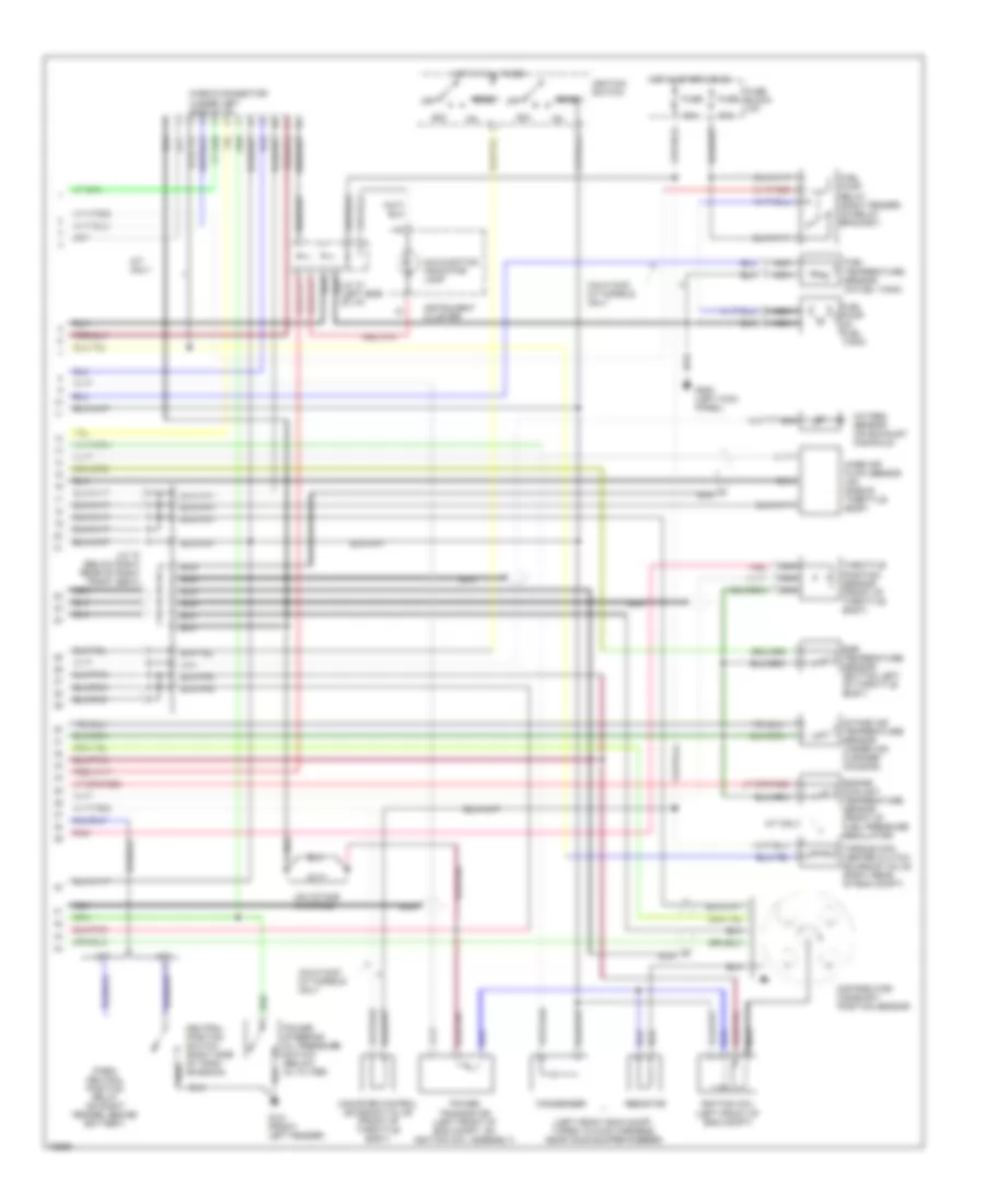
2.4L, Engine Performance Wiring Diagrams (1 of 2) for Nissan Pickup SE 1995

List of elements for 2.4L, Engine Performance Wiring Diagrams (1 of 2) for Nissan Pickup SE 1995:
- (a/c relay)
- (bottom left of throttle body)
- (left rear of throttle body)
- (tach)
- 15a
- A/c system
- A/c system (a/c relay)
- A/c system (low pressure switch)
- A/t only
- Calif 2wd m/t models only
- Canister purge control valve (calif 2wd m/t models only) (right rear of eng compt)
- Closed throttle position switch (front of throttle body)
- Eccs relay (right side of eng compt, on relay bracket)
- Egr valve & canister control solenoid valve (except calif 2wd m/t)
- Egrc- solenoid valve (calif 2wd m/t)
- Engine control module (ecm) (under front passenger's seat)
- Fuel injectors
- Fuse
- Fuse block (i/p)
- Fuse block (right side of eng compt, on relay bracket)
- G301 (below right front seat)
- Hot at all times
- Hot in start
- Iacv-aac valve
- Iacv-ficd solenoid valve (left side of throttle body)
- Instrument cluster system
- Instrument cluster system (speed sens)
- Nca
- No.1
- No.2
- No.3
- No.4
- Or on
- Pairc- solenoid valve (left front of eng compt)
- Pnk
- Red
- Scv control solenoid valve (under intake manifold collector)
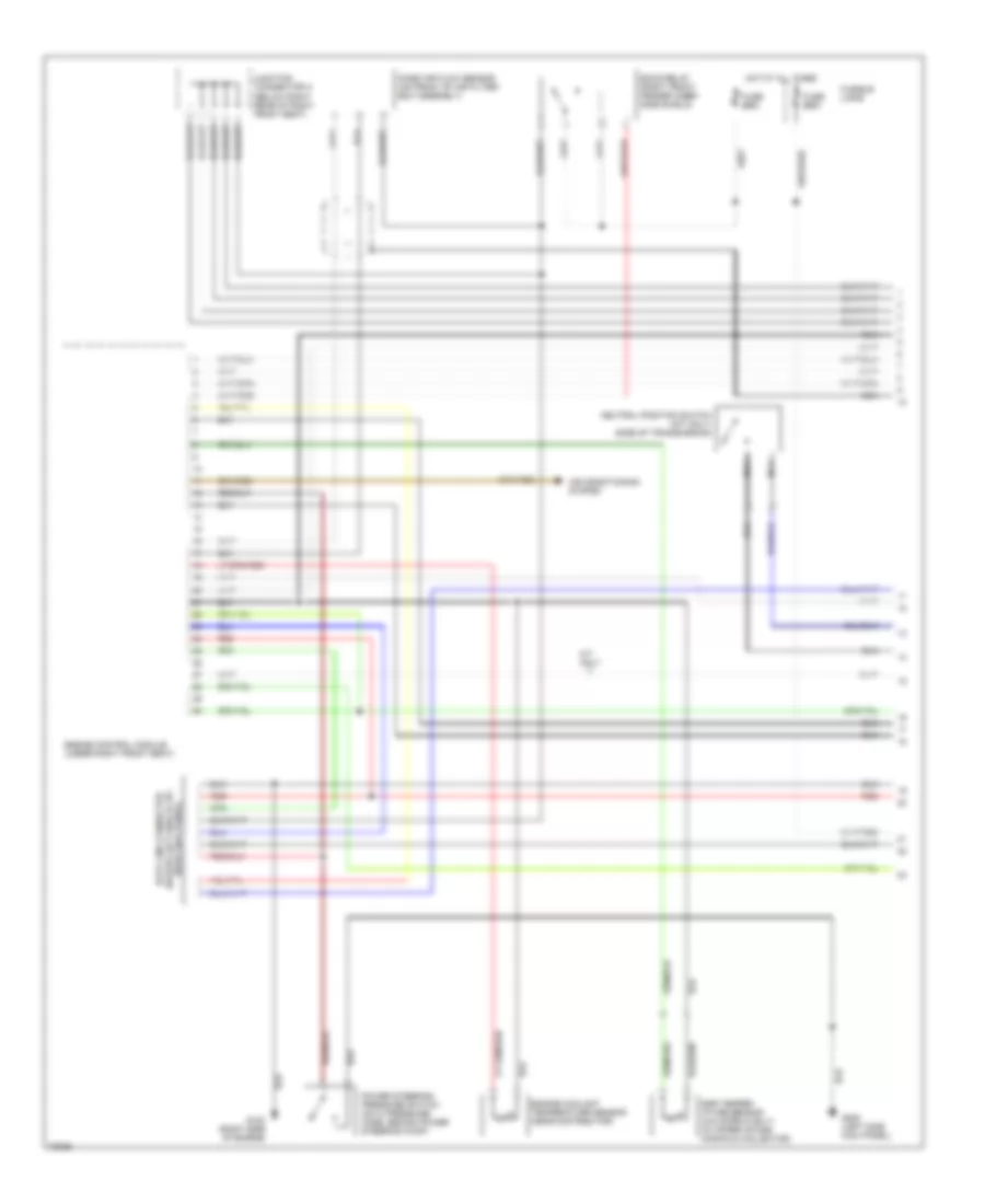
2.4L, Engine Performance Wiring Diagrams (2 of 2) for Nissan Pickup SE 1995
List of elements for 2.4L, Engine Performance Wiring Diagrams (2 of 2) for Nissan Pickup SE 1995:
- (left front eng compt, taped to main harness, near hood bumper rubber)
- (on intake manifold)
- 10a
- A/t
- A/t only
- Acc
- Calif 2wd m/t models only
- Canister control solenoid valve (front of throttle body)
- Check connector (under left side of i/p)
- Condenser
- Distributor/ camshaft position sensor
- Egr temperature sensor (bottom left of throttle body)
- Engine coolant temperature sensor (front of fuel pressure regulator)
- Fuel pump (in fuel tank)
- Fuel pump relay (right fender, on relay bracket)
- Fuel temperature sensor (in fuel tank)
- Fuse
- Fuse block (i/p)
- G101 (front left fender)
- G131
- G200 (left kick panel)
- Hot at all times
- Hot in start or on
- Ignition coil (left front of eng compt)
- Ignition switch
- Instrument cluster
- Intake air temperature sensor (under air cleaner housing)
- J/c "a" (below right rear of right front seat)
- M/t
- Malfunction indicator lamp
- Mass air flow sensor (on side of throttle body)
- Nca
- Neutral position switch (right side of tran- smission)
- Off
- Oxygen sensor (on exhaust manifold)
- Park/ neutral position relay (on right fender, behind battery)
- Pnk
- Power steering oil pressure switch (below oil filter)
- Power transistor (left front of eng compt, on ignition coil assembly)
- Resistor
- Start
- Throttle position sensor (front of throttle body)
- Torque con- verter clutch solenoid valve (right rear of eng compt)
3.0L
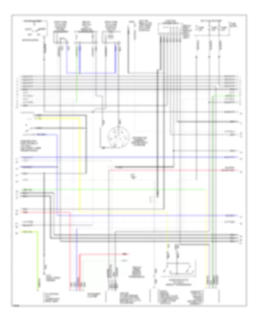
3.0L, Engine Performance Wiring Diagrams (1 of 3) for Nissan Pickup SE 1995
List of elements for 3.0L, Engine Performance Wiring Diagrams (1 of 3) for Nissan Pickup SE 1995:
- (below left side of i/p, near kick panel)
- (below right rear of right front seat)
- Air conditioning system
- Connector a
- Data link connector
- Eccs relay (right front fender inner side shield)
- Egr temper- ature sensor (california only) (in upper intake manifold collector)
- Engine control module (under right front seat)
- Engine coolant temperature sensor (near distributor)
- Fusible links
- G120 (right side of engine)
- G200 (left side kick panel)
- Hot at all times
- Junction
- M/t only
- Mass air flow sensor (on front of air filter/ box assembly)
- Nca
- Neutral position switch (m/t only) (side of transmission)
- Power steering pressure switch (on hi pressure hose, behind power steering pump)
- Red
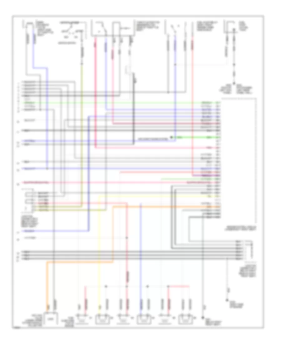
3.0L, Engine Performance Wiring Diagrams (2 of 3) for Nissan Pickup SE 1995
List of elements for 3.0L, Engine Performance Wiring Diagrams (2 of 3) for Nissan Pickup SE 1995:
- (below ignition coil) resistor & condenser
- (below right rear of right front seat)
- (right side of intake manifold) ignition coil
- (right side of intake manifold) power transistor
- A/t control unit (under right front seat
- Acc
- Camshaft position sensor (inside distributor assembly)
- Connector a
- Distributor assembly (center front of engine)
- Fuse 10a
- Fuse 15a
- Fuse block
- G101 (right front fender)
- Heated oxygen sensor (in exhaust pipe, before catalytic converter)
- Hot at all times
- Hot in on or start
- Iacv-air regulator (left rear of intake manifold)
- Ignition switch
- Inhibitor switch (a/t only) (side of transmission)
- Instrument cluster
- Junction
- Knock sensor (center valley of engine block, under intake manifold)
- M/t only
- Nca
- Off
- Park/neutral position relay (a/t only) (left front inner fender shield)
- Red
- Start
- Vehicle speed sensor (side of transmission)
3.0L, Engine Performance Wiring Diagrams (3 of 3) for Nissan Pickup SE 1995
List of elements for 3.0L, Engine Performance Wiring Diagrams (3 of 3) for Nissan Pickup SE 1995:
- Acc
- Air conditioning system
- Egrc solenoid valve (right side of throttle body)
- Engine control module (under right front seat)
- Fuel injectors (top of engine)
- Fuel pump (in fuel tank)
- Fuel pump relay (right front fender inner side shield)
- G120 (right side of engine)
- G200 (pick-up) (left kick panel)
- G301 (below right front seat)
- G402 (pathfinder) (left rear wheel well)
- Hot at all times
- Iacv-aac valve (under upper intake manifold collector)
- Ignition switch
- Junction connector a (below right rear of right front seat)
- Nca
- Off
- Pnk
- Start
- Throttle position sensor/switch (side of throttle body)