ENGINE PERFORMANCE
1.8L
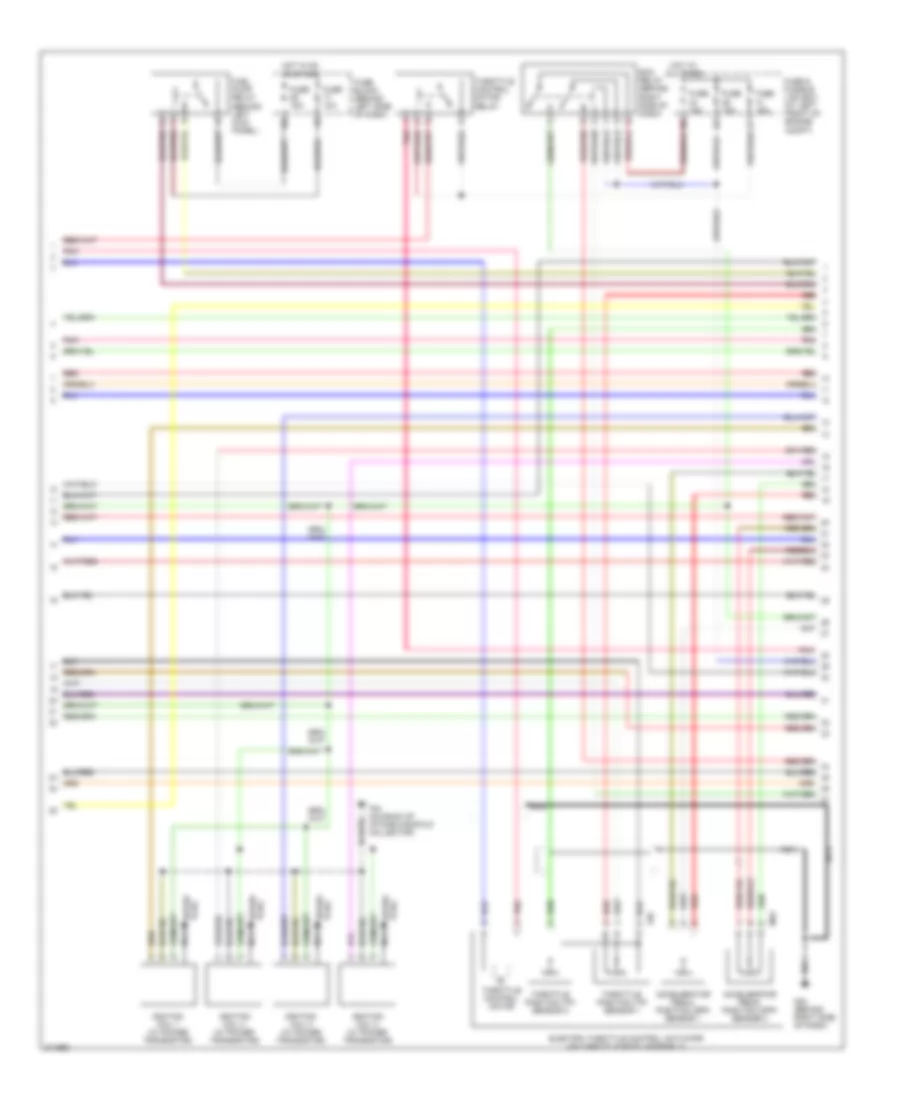
1.8L, Engine Performance Wiring Diagram (1 of 4) for Nissan Sentra S 2005

List of elements for 1.8L, Engine Performance Wiring Diagram (1 of 4) for Nissan Sentra S 2005:
- (behind right side of dash) m54
- (on back of intake manifold collector) f34
- (w/ tach)
- (w/o tach)
- A/f-ip1
- Af-h1
- Af-un1
- Af-vm1
- Avcc
- Avcc-4
- Avcc3
- Combination meter
- Computer data lines system
- Condenser
- Crankshaft position sensor (pos) (on right rear side of cylinder block)
- Cvtc
- Engine control module (on right side of firewall)
- Evap
- Evap canister purge volume control solenoid valve (on top rear of engine)
- Ftrps
- Fuel injector
- Fuse 10a
- Fuse block (behind left side of dash)
- Gnd
- Ho2s2h
- Hot in on or start
- Inj 1
- Inj 2
- Inj 3
- Inj 4
- J/c
- Knk
- Knock sensor (on right side of cylinder block)
- M29
- M30
- M54 (behind right side of dash)
- Malfunction indicator lamp
- Motor1
- Motor2
- Nca
- Phase
- Pnk
- Pos
- Ps pres
- Qa+
- Red
- Refrigerant pressure sensor (on a/c liquid tank)
- Scv1
- Scv2
- Scv3
- Scv4
- Scvps
- Swirl control valve (sulev) (on top rear of engine)
- Tps1
- Unified meter control unit
- Vmot
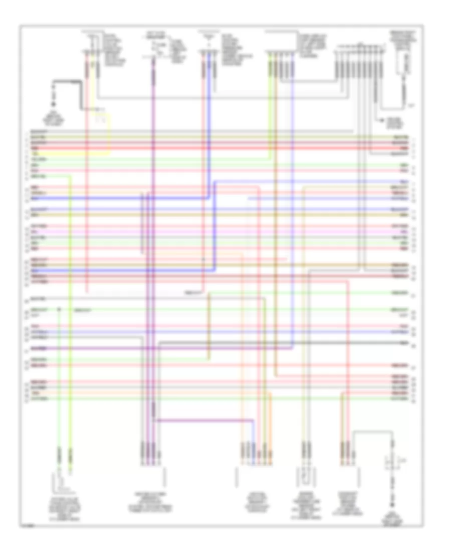
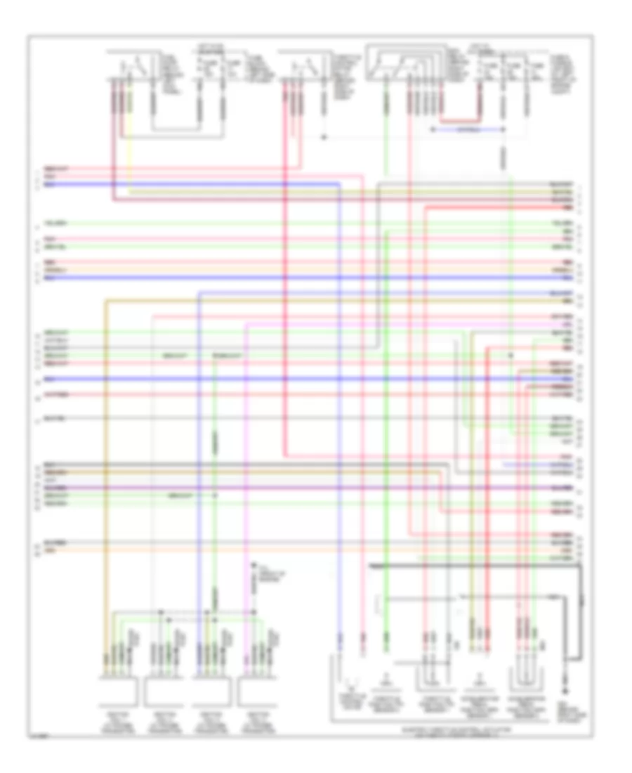
1.8L, Engine Performance Wiring Diagram (2 of 4) for Nissan Sentra S 2005
List of elements for 1.8L, Engine Performance Wiring Diagram (2 of 4) for Nissan Sentra S 2005:
- Accelerator pedal position (app) sensor 1
- Accelerator pedal position (app) sensor 2
- Ecm relay (behind right side of dash)
- Electric throttle control actuator (on throttle body assembly)
- F34 (on back of intake manifold collector)
- F58
- Fuel pump relay (behind left kick panel)
- Fuse & fusible link box (at left front of engine compt)
- Fuse 10a
- Fuse 15a
- Fuse block (behind left side of dash)
- Hot at all times
- Hot in on or start
- Ignition coil 1 (w/ power transistor)
- Ignition coil 2 (w/ power transistor)
- Ignition coil 3 (w/ power transistor)
- Ignition coil 4 (w/ power transistor)
- M54 (behind right side of dash)
- M66
- Nca
- Plug spark
- Pnk
- Red
- Spark plug
- Throttle control motor
- Throttle control motor relay
- Throttle position (tp) sensor 1
- Throttle position (tp) sensor 2
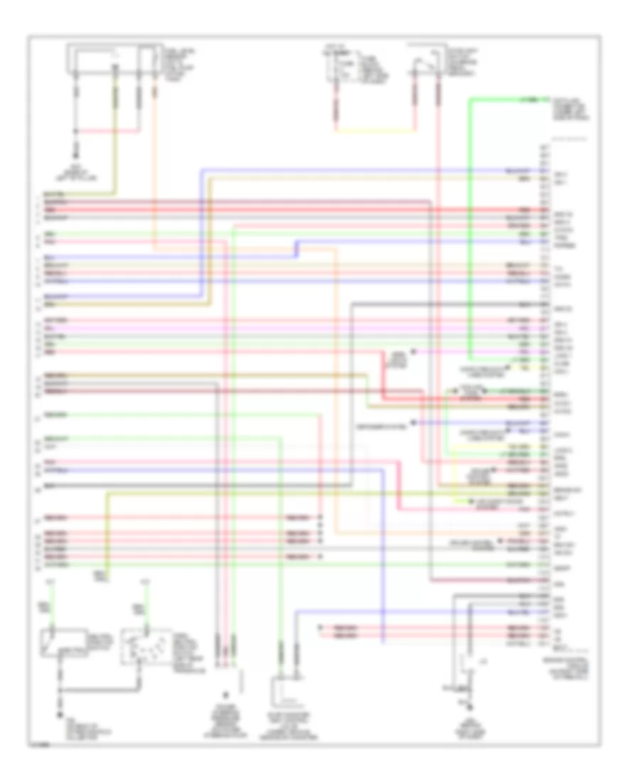
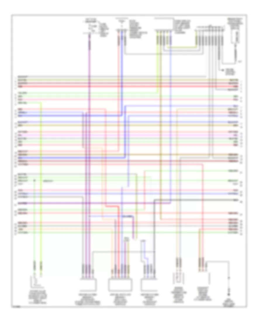
1.8L, Engine Performance Wiring Diagram (3 of 4) for Nissan Sentra S 2005
List of elements for 1.8L, Engine Performance Wiring Diagram (3 of 4) for Nissan Sentra S 2005:
- (behind right kick panel) transmission control module
- 13k
- A/t
- Air fuel ratio (a/f) sensor 1 (on exhaust manifold)
- Camshaft position sensor (phase) (at rear of cylinder head)
- Cruise control system
- Engine coolant temperature sensor (on left front side of cylinder head)
- Evap control system pressure sensor (under vehicle, near evap canister)
- Fuse 15a
- Fuse block (behind left side of dash)
- Heated oxygen sensor 2 (on exhaust system, downstream three way catalyst)
- Hot in on or start
- Intake valve timing control solenoid valve (on right front side of cylinder head)
- J/c
- M54 (behind right side of dash)
- Mass airflow (maf) sensor (at left side of eng compt, on air cleaner)
- Nca
- Pnk
- Red
- Sens gnd
- Swirl control valve position sensor (sulev) (on intake manifold)
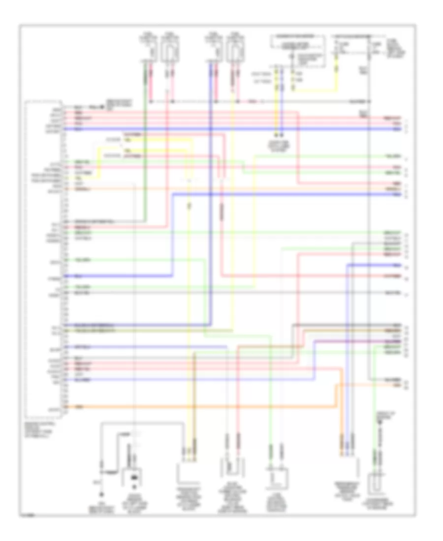
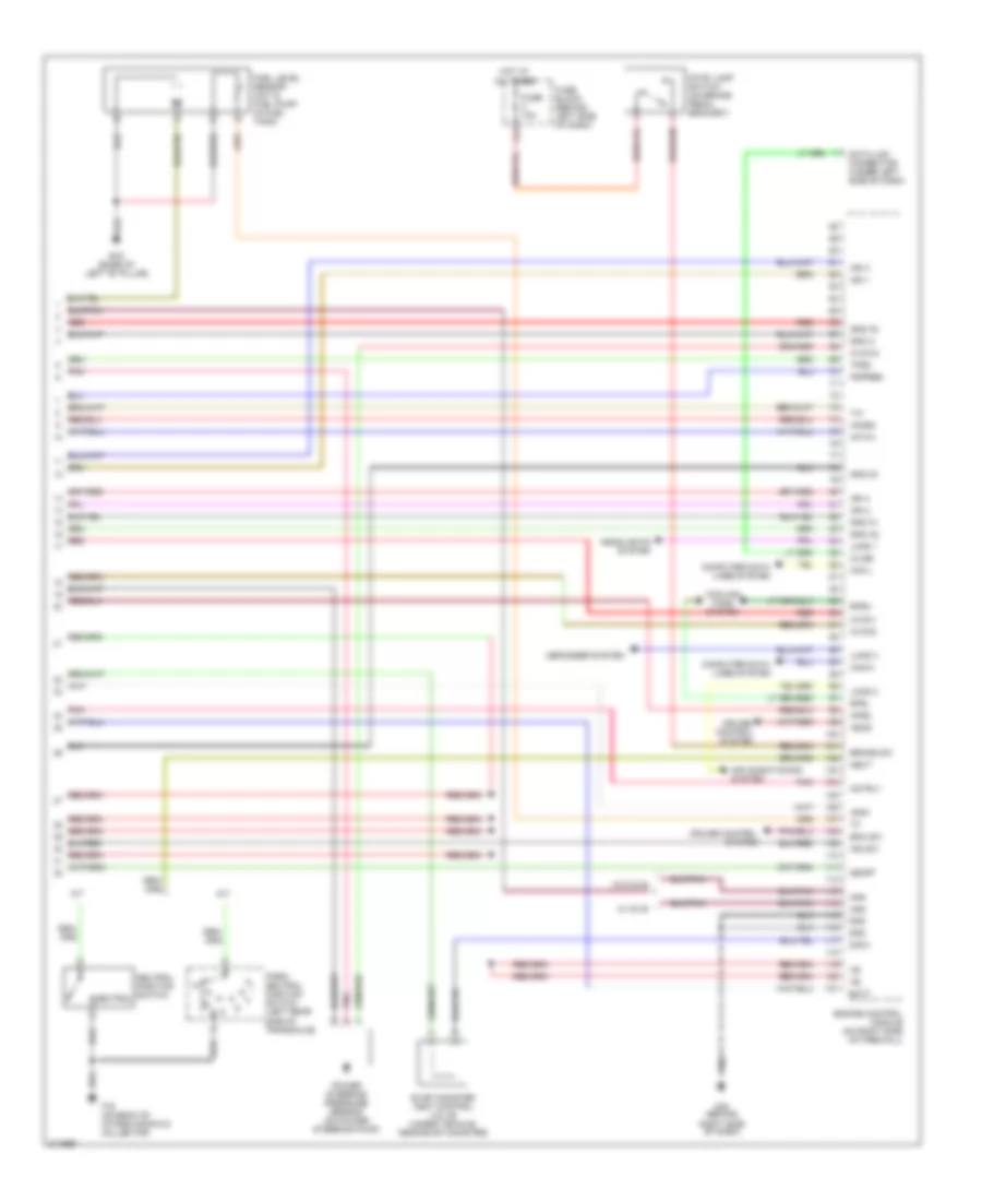
1.8L, Engine Performance Wiring Diagram (4 of 4) for Nissan Sentra S 2005
List of elements for 1.8L, Engine Performance Wiring Diagram (4 of 4) for Nissan Sentra S 2005:
- 11l
- A/f-ia1
- A/t
- Air conditioning system
- Aps1
- Aps2
- Ascd
- Avcc-5
- Avcc1
- Avcc2
- B19 (base of left "b" pillar)
- Batt
- Bnc sw
- Brake sw
- Can l
- Can-h
- Cdcv
- Computer data lines system
- Cooling fans system
- Cruise control system
- Data link connector (under left side of dash)
- Defogger system
- Engine control module (on right side of firewall)
- Evap canister vent control valve (under vehicle, near evap canister)
- F36 (on back of intake manifold collector)
- Fpr
- Fuel level sensor unit & fuel pump (in fuel tank)
- Fuse 10a
- Fuse block (behind left side of dash)
- Gnd
- Gnd 02
- Gnd a
- Gnd a1
- Gnd a2
- Gnd a3
- Head- lights system
- Ho2s2
- Hot at all times
- Ign 1
- Ign 2
- Ign 3
- Ign 4
- Ign sw
- J/c
- Kline
- Load 1
- Load 2
- M/t
- M54 (behind right side of dash)
- Motrly
- Neut
- Neutral
- Neutral position switch
- Park/ neutral position switch (left rear side of transaxle)
- Pdpres
- Pnk
- Power steering pressure sensor (on power steering pump)
- Red
- Rfrh
- Rfrl
- Ssoff
- Stoplight switch (on brake pedal bracket)
- Tps2
2.5L
2.5L, Engine Performance Wiring Diagram (1 of 4) for Nissan Sentra S 2005
List of elements for 2.5L, Engine Performance Wiring Diagram (1 of 4) for Nissan Sentra S 2005:
- (behind right side of dash) m54
- (front of engine) f14
- (w/ tach)
- (w/o tach)
- A/f-ip1
- Af-h1
- Af-un1
- Avcc
- Avcc-4
- Avcc3
- Cdvc
- Combination meter
- Computer data lines system
- Condenser (top right rear of engine)
- Crankshaft position sensor (pos) (on rear of cylinder block)
- Cvtc
- Engine control module (on right side of firewall)
- Evap
- Evap canister purge volume control solenoid valve (right rear side of engine)
- Ftrps
- Fuel injector
- Fuse 10a
- Fuse block (behind left side of dash)
- Gnd
- Ho2s1
- Ho2s1h
- Ho2s2h
- Hot in on or start
- Inj 1
- Inj 2
- Inj 3
- Inj 4
- Knk
- Knock sensor (on left side of cylinder block)
- M29
- M30
- M54 (behind right side of dash)
- Malfunction indicator lamp
- Motor1
- Motor2
- Nca
- Pnk
- Pos (or phase)
- Ps pres
- Qa+
- Red
- Refrigerant pressure sensor (on a/c liquid tank)
- Tps1
- Unified meter control unit
- Vias control solenoid (on intake manifold)
- Vmot
2.5L, Engine Performance Wiring Diagram (2 of 4) for Nissan Sentra S 2005
List of elements for 2.5L, Engine Performance Wiring Diagram (2 of 4) for Nissan Sentra S 2005:
- Accelerator pedal position (app) sensor 1
- Accelerator pedal position (app) sensor 2
- Ecm relay (behind right side of dash)
- Electric throttle control actuator (on throttle body assembly)
- F14 (front of engine)
- F50
- Fuel pump relay (behind left kick panel)
- Fuse & fusible link box (at left front of engine compt)
- Fuse 10a
- Fuse 15a
- Fuse block (behind left side of dash)
- Hot at all times
- Hot in on or start
- Ignition coil 1 (w/ power transistor)
- Ignition coil 2 (w/ power transistor)
- Ignition coil 3 (w/ power transistor)
- Ignition coil 4 (w/ power transistor)
- M54 (behind right side of dash)
- M66
- Nca
- Plug spark
- Pnk
- Red
- Spark plug
- Throttle control motor
- Throttle control motor relay (behind right side of dash)
- Throttle position (tp) sensor 1
- Throttle position (tp) sensor 2
2.5L, Engine Performance Wiring Diagram (3 of 4) for Nissan Sentra S 2005
List of elements for 2.5L, Engine Performance Wiring Diagram (3 of 4) for Nissan Sentra S 2005:
- (behind right kick panel) transmission control module
- 13k
- A/t
- Air fuel ratio (a/f) sensor 1 (exc ulev) (on exhaust manifold)
- Camshaft position sensor (phase) (at rear of cylinder head)
- Cruise control system
- Engine coolant temperature sensor (front of intake manifold)
- Evap control system pressure sensor (under vehicle, near evap canister)
- Exc ulev
- Fuse 15a
- Fuse block (behind left side of dash)
- Heated oxygen sensor 1 (ulev) (on exhaust manifold)
- Heated oxygen sensor 2 (on exhaust system, downstream three way catalyst)
- Hot in on or start
- Intake valve timing control solenoid valve (on right front side of cylinder head)
- J/c
- M54 (behind right side of dash)
- Mass airflow (maf) sensor (at left side of eng compt, on air cleaner)
- Pnk
- Red
- Sens gnd
- Ulev
2.5L, Engine Performance Wiring Diagram (4 of 4) for Nissan Sentra S 2005
List of elements for 2.5L, Engine Performance Wiring Diagram (4 of 4) for Nissan Sentra S 2005:
- 11l
- A/f-ia1
- A/t
- Air conditioning system
- Aps1
- Aps2
- Ascd
- Avcc-5
- Avcc1
- Avcc2
- B19 (base of left "b" pillar)
- Batt
- Bnc sw
- Brake sw
- Can l
- Can-h
- Cdcv
- Computer data lines system
- Cooling fans system
- Cruise control system
- Data link connector (under left side of dash)
- Defogger system
- Engine control module (on right side of firewall)
- Evap canister vent control valve (under vehicle, near evap canister)
- F16 (on back of intake manifold collector)
- Fpr
- Fuel level sensor unit & fuel pump (in fuel tank)
- Fuse 10a
- Fuse block (behind left side of dash)
- Gnd
- Gnd 02
- Gnd a
- Gnd a1
- Gnd a2
- Gnd a3
- Headlights system
- Ho2s2
- Hot at all times
- Ign 1
- Ign 2
- Ign 3
- Ign 4
- Ign sw
- Kline
- Load 1
- Load 2
- Load 3
- M/t
- M54 (behind right side of dash)
- Motrly
- Neut
- Neutral
- Neutral position switch
- Park/ neutral position switch (left rear side of transaxle)
- Pdpres
- Pnk
- Power steering pressure sensor (on power steering pump)
- Red
- Rfrh
- Rfrl
- Ssoff
- Stop lamp switch (on brake pedal bracket)
- Tps2
- W/ nvis
- W/o nvis