ENGINE PERFORMANCE
2.0L
2.0L, Engine Performance Wiring Diagram (1 of 3) for Suzuki Aerio GS 2003

List of elements for 2.0L, Engine Performance Wiring Diagram (1 of 3) for Suzuki Aerio GS 2003:
- A/c, trans- missions systems
- Assembly)
- C45
- C46
- Egr stepper motor (on rear of engine)
- Engine control module (behind glove box)
- Evap canister purge valve (at rear of engine, near egr stepper motor)
- Fuel pump & gauge (in fuel tank)
- Fuel pump relay (on relay box)
- Fuse 15a
- Fuse box
- G20 (near right side of fuel tank)
- G3 (on intake manifold)
- G4 (on intake manifold
- Hot at all times
- Hot in run or start
- Idle air control valve (on throttle body
- Knock sensor (right side of engine)
- Main fuse
- Main relay (on relay box)
- Pnk
- Power steering pump pressure switch (on power steering pump)
- Red
- Starting/charging system
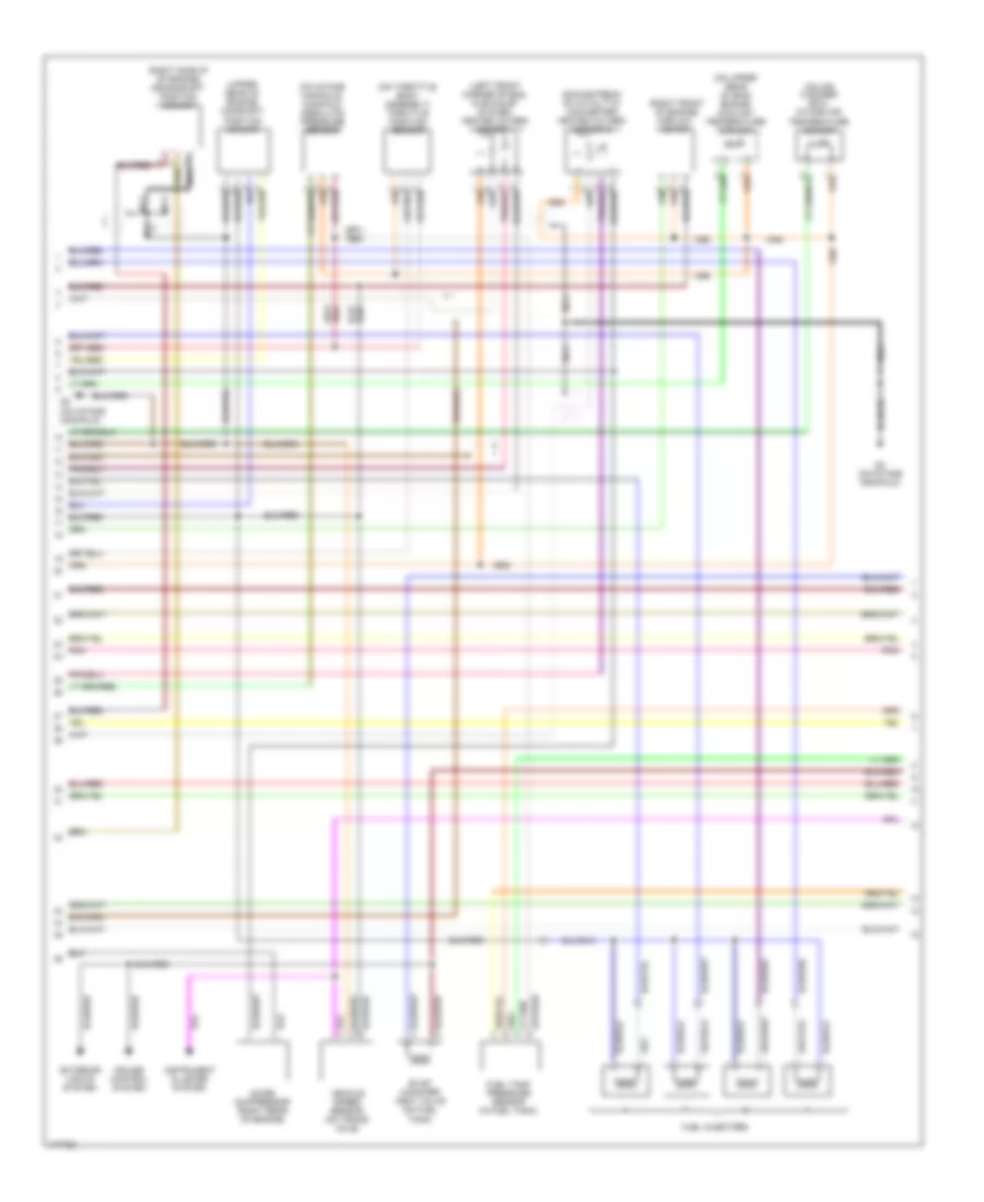
2.0L, Engine Performance Wiring Diagram (2 of 3) for Suzuki Aerio GS 2003
List of elements for 2.0L, Engine Performance Wiring Diagram (2 of 3) for Suzuki Aerio GS 2003:
- (downstream of catalytic converter) heated oxygen sensor 2
- (left front corner of eng, in exhaust system) heated oxygen sensor 1
- (on air cleaner box) intake air temperature sensor
- (on intake manifold)
- (on intake manifold) manifold absolute pressure sensor
- (on throttle body assembly) throttle position sensor
- (on upper rear of eng) engine coolant temperature sensor
- (right front of engine) airflow meter
- (right side of of engine) crankshaft position sensor
- (upper rear of engine) camshaft position sensor
- Cruise control system
- Evap canister vent valve (on fuel tank)
- Exterior lights system
- Fuel injectors
- Fuel tank pressure sensor (in fuel tank)
- G3 (on intake manifold)
- Instrument cluster system
- Nca
- Noise suppressor (right rear of engine)
- Pnk
- Vehicle speed sensor (on trans- axle)
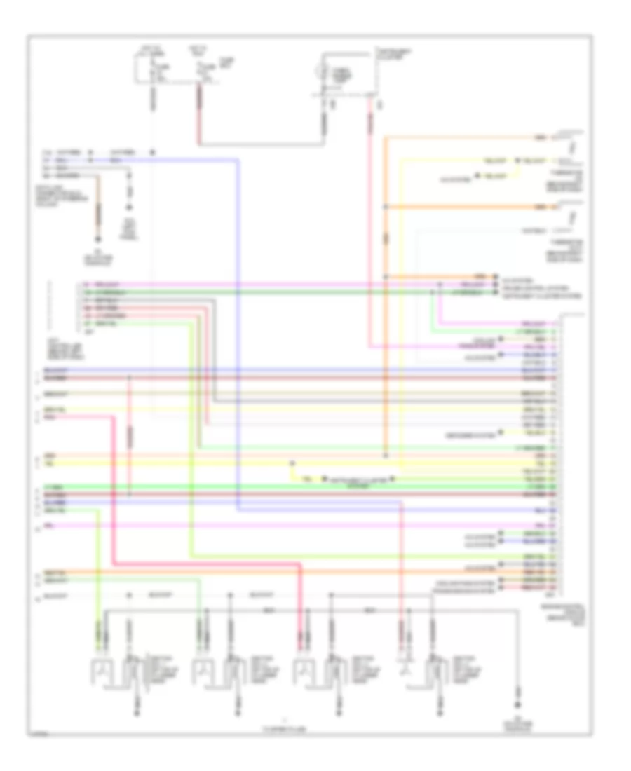
2.0L, Engine Performance Wiring Diagram (3 of 3) for Suzuki Aerio GS 2003
List of elements for 2.0L, Engine Performance Wiring Diagram (3 of 3) for Suzuki Aerio GS 2003:
- 4a/t controller (behind left side of dash)
- A/c system
- Check engine lamp
- Cooling fans system
- Cruise control system
- Data link connector (dlc) (right of steering column)
- Defogger system
- Engine control module (behind glove box)
- Fuse 10a
- Fuse 15a
- Fuse box
- G04
- G07
- G13 (left kick panel)
- G20
- G21
- G3 (on intake manifold)
- G4 (on intake manifold)
- Hot at all times
- Hot in run
- Ignition coil 1 (on top of cylinder head)
- Ignition coil 2 (on top of cylinder head)
- Ignition coil 3 (on top of cylinder head)
- Ignition coil 4 (on top of cylinder head)
- Instrument cluster
- Instrument cluster system
- Nca
- Pnk
- Thermistor (in) (behind right side of dash)
- Thermistor (out) (behind right side of dash)
- To spark plugs
- Transmissions system