ENGINE PERFORMANCE
1.6L
1.6L, Engine Performance Wiring Diagrams, 4 Speed A/T (1 of 3) for Suzuki X-90 1998

List of elements for 1.6L, Engine Performance Wiring Diagrams, 4 Speed A/T (1 of 3) for Suzuki X-90 1998:
- combination meter
- 4wd ind
- 4wd switch
- Abs controller
- Air conditioning system
- Brake light switch (on bracket, above brake pedal)
- Camshaft position (cmp) sensor
- Combination meter
- Crankshaft position sensor (ckp) (on eng front cover)
- Cruise control module
- Distributor
- E174
- E175
- E44
- Egr solenoid vacuum valve (on right side of eng)
- Fuse 15a
- Fuse 16 15a
- Fuse box
- G09
- G11
- G117 (right rear of eng)
- G121 (center of firewall)
- G205 (right side of steering column)
- Hot at all times
- Hot in start or on
- Igniter
- Ignition coil
- J/c (e118) (behind left side of dash)
- J/c (e179) (near left kick panel)
- J/c (g32) (behind left side of dash)
- Main fuse box
- Main relay (behind right center of dash, in relay block)
- Mal- function indicator lamp
- Noise suppressor filter (left rear of eng compt)
- O/d off ind
- P/n ind
- Pnk
- Power steering pump pressure switch (on power steering pump assembly)
- Powertrain control module (behind dash, on steering column)
- Throttle position (tp) sensor (on throttle body)
- To spark plugs
- Vehicle speed sensor
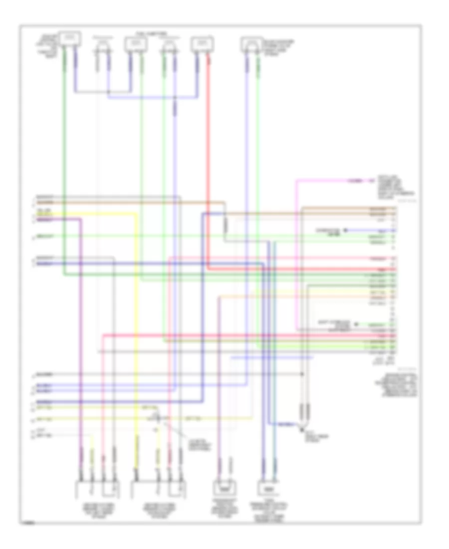
1.6L, Engine Performance Wiring Diagrams, 4 Speed A/T (2 of 3) for Suzuki X-90 1998
List of elements for 1.6L, Engine Performance Wiring Diagrams, 4 Speed A/T (2 of 3) for Suzuki X-90 1998:
- (on air cleaner assembly)
- Acc
- Diagnosis coupler (on right inner fender panel, behind headlight)
- Egr check vacuum solenoid valve (on right side of firewall)
- Engine coolant temperature (ect) sensor (on intake manifold)
- Evap canister air vent control valve (on right inner fender panel)
- Fuel pump (in fuel tank)
- Fuel pump relay (behind right center of dash, in relay box)
- Fuse 11 15a
- Fuse 17 15a
- Fuse box
- G205 (right side of steering column)
- G402 (above left rear wheel- well)
- Headlight relay 2 (behind side of dash)
- Hot at all times
- Hot in on or start
- Ignition switch
- Intake air temperature (iat) sensor (on air cleaner housing)
- J/c (e118) (behind left side of dash)
- J/c (e178) (behind center of dash)
- J/c (e179) (near left kick panel)
- J/c (e179) (right kick panel)
- Lock
- Manifold absolute pressure (map)
- Mass airflow sensor
- Pnk
- Sensor (on right side of firewall)
- Sensor (on underside of vehicle, near fuel tank)
- Shift solenoid valves & tcc solenoid valve (on transmission housing)
- Start
- Tank pressure
- Tank pressure control solenoid vacuum valve (on right inner fender panel)
1.6L, Engine Performance Wiring Diagrams, 4 Speed A/T (3 of 3) for Suzuki X-90 1998
List of elements for 1.6L, Engine Performance Wiring Diagrams, 4 Speed A/T (3 of 3) for Suzuki X-90 1998:
- (right rear of eng)
- (right rear of engine)
- 4wd low switch
- Connector (under left side of dash, right of steering column)
- Cruise control system
- Data link
- E172
- E173
- Evap canister purge valve (on right side of eng)
- Fuel injectors
- G117
- G200
- G202
- Heated oxygen sensor 1 (ho2s1) (on left rear of eng)
- Heated oxygen sensor 2 (ho2s2) (on exhaust system)
- Idle air control (iac) valve (on throttle body)
- Illum.
- Interior lights system
- J/c (e114) (left side of dash)
- Nca
- Overdrive off switch
- P/n switch contaeur
- Pnk
- Powertrain control module (behind dash, on steering column)
- Red
- Shift interlock system
- Starting/ charging system
- Transmission range switch (on transmission assembly)
- Vehicle speed sensor (on transmission assembly)
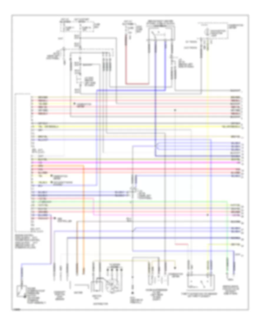
1.6L, Engine Performance Wiring Diagrams, M/T & 3 Speed A/T (1 of 3) for Suzuki X-90 1998
List of elements for 1.6L, Engine Performance Wiring Diagrams, M/T & 3 Speed A/T (1 of 3) for Suzuki X-90 1998:
- (3 a/t)
- (a/t)
- (behind right center of dash, in relay block) main relay
- (m/t)
- (m/t) (3 a/t)
- (w/ tacho)
- (w/o tacho)
- Abs controller
- Air conditioning system
- Camshaft position (cmp) sensor
- Combination meter
- Distributor
- E32 e174
- E34 e175
- E44
- Egr solenoid vacuum valve (on right side of eng)
- Engine control module (ecm) powertrain control module (pcm) (behind dash, on steering column)
- Fuse 11 15a
- Fuse 15a
- Fuse 16 15a
- Fuse box
- G09
- G11
- G121 (center of firewall)
- Hot at all times
- Hot in start or on
- Igniter
- Ignition coil
- J/c (e118) (behind left side of dash)
- J/c (e179) (near left kick panel)
- J/c (g32) (behind left side of dash)
- Main fuse box
- Malfunction indicator lamp
- Noise suppressor filter (left rear of eng compt)
- Pnk
- Power steering pump pressure switch (on power steering pump assembly)
- Throttle position (tp) sensor (on throttle body)
- To spark plugs
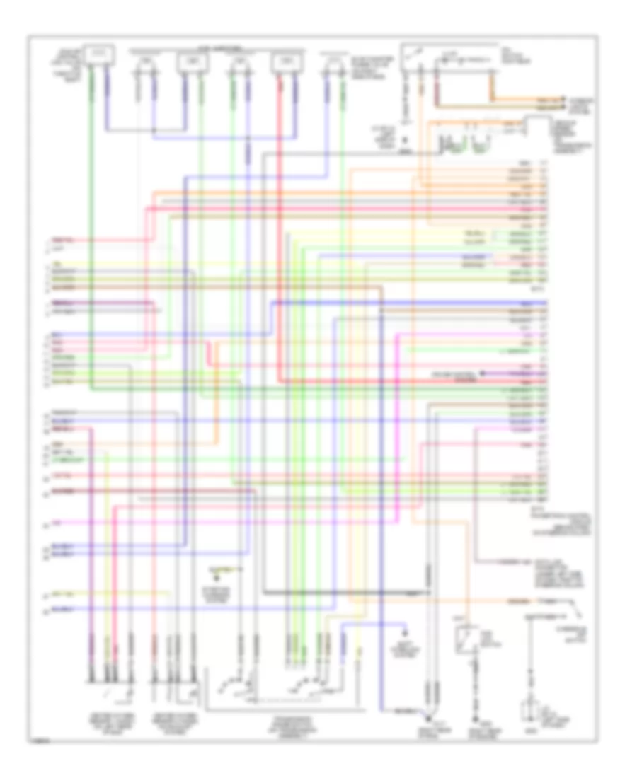
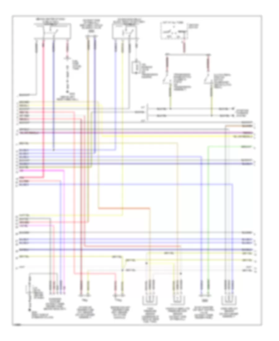
1.6L, Engine Performance Wiring Diagrams, M/T & 3 Speed A/T (2 of 3) for Suzuki X-90 1998
List of elements for 1.6L, Engine Performance Wiring Diagrams, M/T & 3 Speed A/T (2 of 3) for Suzuki X-90 1998:
- (above left rear wheelwell)
- (behind center of dash, in relay box) main relay
- (ect) sensor (on intake manifold)
- (on air cleaner assembly)
- (on eng room relay block, front of battery) tcc relay
- (on right side of firewall) egr check vacuum solenoid valve
- A/t
- Acc
- Clutch pedal position switch (on bracket. above clutch pedal)
- Diagnosis coupler (on right inner fender panel. behind headlight)
- Engine coolant temperature
- Evap canister air vent control valve (on right inner fender panel)
- Fuel pump (in fuel tank)
- G205 (right side of steering column)
- G402
- Hot at all times
- Ignition switch
- Intake air temperature (iat) sensor (on air cleaner assembly)
- J/c (e178) (behind center of dash)
- Lock
- M/t
- Manifold absolute pressure (map)
- Mass airflow sensor
- Pnk
- Sensor (on right side of firewall)
- Sensor (underside of vehicle, near fuel tank)
- Start
- Starting/ charging system
- Tank pressure
- Tcc solenoid valve (on transmission housing)
- Transmission range switch (closed in p or n) (on transmission) assembly)
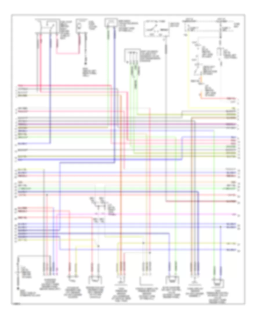
1.6L, Engine Performance Wiring Diagrams, M/T & 3 Speed A/T (3 of 3) for Suzuki X-90 1998
List of elements for 1.6L, Engine Performance Wiring Diagrams, M/T & 3 Speed A/T (3 of 3) for Suzuki X-90 1998:
- (m/t) (3 a/t)
- Combination meter
- Crankshaft position sensor (ckp) (on eng front cover)
- Data link connector (under left side of dash, right of steering column)
- E172
- E33
- Engine control (m/t) powertrain control (a/t) (behind dash, on steering column)
- Evap canister purge valve (right side of eng)
- Fuel injectors
- G117 (right rear of eng)
- Heated oxygen sensor 1 (ho2s1) (on left rear of eng)
- Heated oxygen sensor 2 (ho2s2) (on exhaust system)
- Idle air control (iac) valve (on throttle body)
- J/c (e179) (near right kick panel)
- Module (ecm)
- Module (pcm)
- Nca
- Pnk
- Red
- Shift interlock system (3 a/t only)
- Tank pressure control solenoid vacuum valve (on right inner fender panel)