
HORN
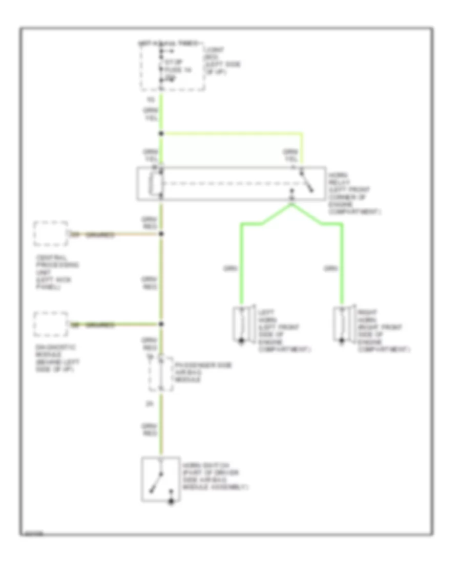
Horn Wiring Diagram for Mazda 929 1995
List of elements for Horn Wiring Diagram for Mazda 929 1995:
AIR CONDITIONINGBODY COMPUTERANTI-THEFTCOMPUTER DATA LINESDEFOGGERSANTI-LOCK BRAKESHEADLIGHTSCRUISE CONTROLENGINE PERFORMANCEEXTERIOR LIGHTSGROUND DISTRIBUTIONHORNINTERIOR LIGHTSPOWER DOOR LOCKSINSTRUMENT CLUSTERPOWER TOP/SUNROOFPOWER SEATSPOWER WINDOWSSHIFT INTERLOCKSPOWER DISTRIBUTIONPOWER MIRRORSSTARTING/CHARGINGRADIOSUPPLEMENTAL RESTRAINTSTRANSMISSIONTRUNK, TAILGATE, FUEL DOORWARNING SYSTEMSWIPER/WASHER