INSTRUMENT CLUSTER
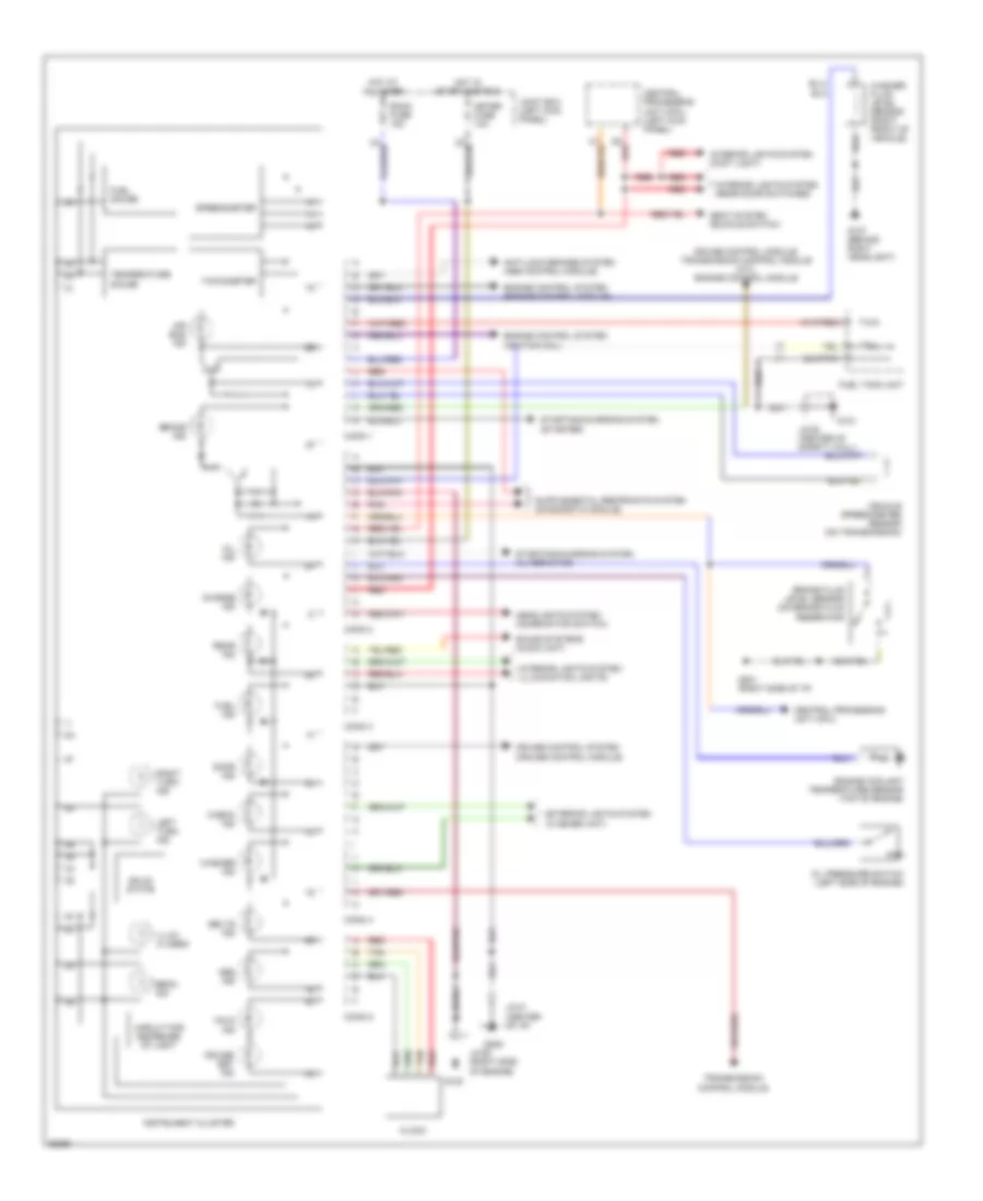
Instrument Cluster Wiring Diagram for Mazda 929 1995
List of elements for Instrument Cluster Wiring Diagram for Mazda 929 1995:
- 2d red
- Abs ind
- Air bag ind
- Anti-lock brakes system (abs control module)
- Beam ind
- Belts ind
- Brake fluid level sensor (on brake fluid reservoir)
- Brake ind
- Central processing unit (cpu)
- Central processing unit (cpu) (left kick panel)
- Charge ind
- Check ind
- Circuit for decrease of light
- Clock
- Conn 1
- Conn 2
- Conn 3
- Conn 4
- Conn 5
- Cruise control module, transmission control module (a/t), engine control module
- Cruise control system (cruise control module)
- Cruise set ind
- Door ind
- Engine control system (engine control module)
- Engine control system (ignition coil)
- Engine coolant temperature sensor (top of engine)
- Exterior lights system (flasher unit)
- Fuel gauge
- Fuel ind
- Fuel tank unit
- G107 (behind right headlight)
- G120
- G121
- G201 (right side of i/p)
- G206
- Headlights system (combination switch)
- Hold ind
- Hot at all times
- Hot in start and run
- Illum (4 used)
- Instrument cluster
- Interior lights system (foot light)
- Interior lights system (illumination lights)
- Interior lights system (rear door switches)
- Jc-01 (center of i/p)
- Jc-05 (center of safety wall)
- Jc-06 (right side of engine)
- Joint box (left kick panel)
- Left turn ind
- Meter fuse 10a
- Oil ind
- Oil pressure switch (left side of engine)
- Pnk
- Rear ind
- Red
- Right turn ind
- Room fuse 15a
- Seat system (buckle switch)
- Solid state
- Sound systems (audio unit)
- Speedometer
- Starting/charging system (alternator)
- Starting/charging system (starter)
- Tachometer
- Tan
- Temperature gauge
- Transmission control module
- Vehicle speedometer sensor (on transmission)
- Washer fluid level sensor (right front of vehicle)
- Washer ind
 English