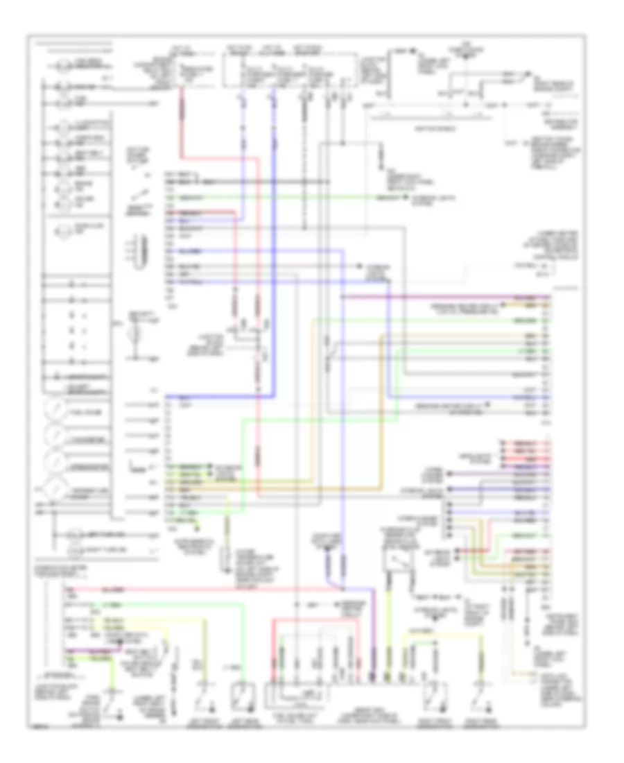
INSTRUMENT CLUSTER
Instrument Cluster Wiring Diagram, Base for Mitsubishi Diamante VR-X 2004

List of elements for Instrument Cluster Wiring Diagram, Base for Mitsubishi Diamante VR-X 2004:
- (ignition timing) engine speed check connector (in engine compt, left side of firewall)
- (on driver's seat belt buckle)
- (sport shift)
- (standard)
- (under front left kick panel)
- (under right front kick panel) g12
- Abs indicator
- Air conditioning system
- Assist ecm (under right side of dash near kick panel)
- B109
- B110
- B23
- B49
- B53
- B54
- B76
- B77
- B78
- B80
- B84
- B86
- B89
- B90
- Brake fluid level sensor (in brake fluid reservoir)
- Brake indicator
- C03
- C04
- C05
- C10
- C11
- Check engine indicator
- Combination meter
- Computer data lines system
- Cruise ctrl ind
- Data link connector (under left side of dash, near steering column)
- Dedicated fuse 11 15a
- Distributor assembly
- Door ajar indicator
- Door switch
- Engine compartment relay box (on left front fender)
- Engine controls system
- Etacs ecu
- Except sport shift
- Exterior lights system
- Fuel gauge
- Fuel gauge unit (in fuel tank)
- Fuel indicator
- G1 (right front of engine compt)
- G14 (under front of center console)
- G3 (under left front kick panel)
- Headlights system
- High beam indicator
- Hot at all times
- Hot in run or start
- Ignition shields
- Illumination
- Instrument panel ecm (behind left side of dash)
- Interior lights system
- Junction block (behind left side of dash)
- Left front door switch
- Left rear door switch
- Left turn ind
- Message center circuit
- Message center circuit (charge ind)
- Message center circuit (low oil pressure ind)
- Multi- purpose fuse 11 15a
- Multi- purpose fuse 13 10a
- Nca
- Park brake switch (on parking brake assembly)
- Pnk
- Powertrain control module (forward of center console)
- Red
- Right front
- Right rear
- Right turn ind
- Seat belt indicator
- Seat belt switch
- Security indicator
- Speedometer
- Sport shift
- Srs indicator
- Tachometer
- Temperature gauge
- Water temperature gauge unit (on left side of engine compt, near coolant outlet)
- Wiper/ washer system
- Wiper/washer system
Instrument Cluster Wiring Diagram, Up Level for Mitsubishi Diamante VR-X 2004
List of elements for Instrument Cluster Wiring Diagram, Up Level for Mitsubishi Diamante VR-X 2004:
- (ignition timing) engine speed check connector (in engine compt, left side of firewall)
- (in brake fluid reservoir) brake fluid level sensor
- (sports shift)
- (under center of dash, forward of center console) powertrain control module
- (under left side of dash, near steering column)
- A82
- Abs ind
- Air conditioning system
- Assist ecm (under right side of dash, near kick panel)
- B109
- B110
- B23
- B49
- B53
- B54
- B76
- B77
- B78
- B80
- B84
- B86
- B89
- B90
- Brake ind
- C03
- C04
- C10
- Check eng ind
- Combination meter (high-contrast)
- Computer data lines system
- Cpu
- Cruise ind
- Data link connector
- Daytime dimmer switch
- Dedicated fuse 11 15a
- Distributor assembly
- Door ajar ind
- Engine compartment relay box (on left front fender)
- Etacs ecu
- Exterior lights system
- Fuel gauge
- Fuel gauge unit (in fuel tank)
- Fuel ind
- G1 (at right front of engine compt)
- G12 (under right front kick panel, above g13)
- G3 (under left front kick panel)
- G4 (right rear of engine compt)
- Headlights system
- High beam indicator
- Hot at all times
- Hot in on or acc
- Hot in run or start
- Ignition shield
- Illumination lamp
- Instrument panel ecm (behind left side of dash)
- Interior lights system
- Junction block (behind left side of dash)
- L (except sports shift)
- Left front door switch
- Left rear door switch
- Left turn ind
- Member) g6
- Message center circuit
- Message center circuit (charge ind)
- Message center circuit (low oil pressure ind)
- Multi- purpose fuse 11 15a
- Multi- purpose fuse 13 10a
- Multi- purpose fuse 6 10a
- Nca
- Odometer
- Park brake switch (on parking brake assembly)
- Red
- Reset switch
- Right front door switch
- Right rear door switch
- Right turn ind
- Seat belt ind
- Seat belt switch (on driver's seat belt buckle)
- Security ind
- Speedometer
- Srs ind
- Sws
- Tachometer
- Temperature gauge
- Water temperature gauge unit (on left side of engine compt, near coolant outlet)
- Wiper/ washer system
- Wiper/washer system
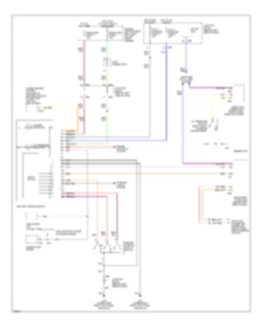
Message Center Wiring Diagram for Mitsubishi Diamante VR-X 2004
List of elements for Message Center Wiring Diagram for Mitsubishi Diamante VR-X 2004:
- (under center of dash, forward of center console) powertrain control module (pcm)
- A42
- Assist ecm (under right side of dash, near kick panel)
- B108
- B23
- B53
- B54
- B77
- B80
- B84
- B86
- C03
- C04
- C10
- Center warning display
- Center warning display switch
- Charge indicator
- Combination meter
- Computer data lines system
- Data link connector (under left side of dash, near steering column)
- Dedicated fuse 11 15a
- Dedicated fuse 2 10a
- Engine compartment relay box (on left front fender)
- Engine controls system
- Etacs ecu
- Fuel gauge unit (in fuel tank)
- G12 (under right front kick panel, above g13)
- Generator
- High-contrast meter
- Hot at all times
- Hot in acc or run
- Hot in run or start
- Hot with taillight relay energized
- Instrument panel ecm (behind left side of dash)
- Interior lights system
- Joint connector 5
- Junction block (behind left side of dash)
- Multi- purpose fuse 13 10a
- Multi- purpose fuse 6 10a
- Oil pressure indicator
- Oil pressure switch (right front of engine compartment)
- Red
- Set
- Solid state
- Standard meter