INSTRUMENT CLUSTER
Instrument Cluster Wiring Diagram (1 of 2) for Mitsubishi Lancer ES 2009

List of elements for Instrument Cluster Wiring Diagram (1 of 2) for Mitsubishi Lancer ES 2009:
- Abs ind
- Beam ind
- Brake ind
- Can transceiver circuit
- Combination meter
- Computer data lines system
- Cpu
- Cruise ind
- Driver's seat belt ind
- Except turbo
- Fog ind
- Fuel level sensor
- Fuel level sensor (sub) (top of fuel tank)
- Fuel pump module (top of fuel tank)
- Fuel tank temperature sensor
- G11 (left side of luggage compt)
- G14 (behind left kick panel)
- G4 (behind right kick panel)
- G5 (right of accelerator pedal)
- Generator malfunction light ind
- Illum
- Interface circuit
- Interior lights system
- Joint connector 6 (behind left side of dash)
- Lcd (abs, acd, asc off, asc operation, asc warning, brake, gravel, snow & tarmac
- Lcd (brake, fuel warning & oil pressure)
- Lcd (cvt position, cvt temperature & cvt failure)
- Lcd (each door)
- Lcd (engine coolant temperature)
- Lcd (generator malfunction light)
- Lcd (key reminder)
- Lcd (kos)
- Lcd (odo/trip, fuel gauge, service reminder, outside temperature & temperature gauge)
- Lcd (shift position, normal sport & s-sport)
- Lcd (theft-alarm ind)
- Lcd (tire pressure)
- Lcd csrs
- Led drive circuit
- Left turn ind
- Malfunction ind light
- Meter information switch
- Parking brake switch (under center console)
- Pnk
- Rheostat
- Right turn ind
- Sound systems
- Speedometer
- Srs ind
- Tachometer
- Tail ind
- Tone alarm
- Turbo
- Warning systems
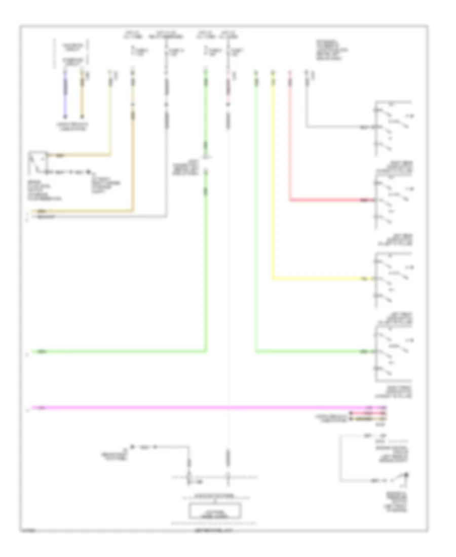
Instrument Cluster Wiring Diagram (2 of 2) for Mitsubishi Lancer ES 2009
List of elements for Instrument Cluster Wiring Diagram (2 of 2) for Mitsubishi Lancer ES 2009:
- Audio switch panel
- B108
- B109
- Brake fluid level switch (on brake fluid reservoir)
- C301
- C312
- C313
- C317
- Can drive circuit
- Center panel unit
- Computer data lines system
- Engine control module (left rear of engine compt)
- Engine oil pressure switch (left front of engine)
- Etacs-ecu (on rear of junction block, behind left end of dash)
- Fuse 12 7.5a
- Fuse 7 15a
- Fuse 8 7.5a
- Fuse 9 15a
- G1 (at right front corner of engine compt)
- G4 (behind right kick panel)
- Hot at all times
- Hot w/ ig1 relay energized
- Interface circuit
- Joint connector 3 (behind left side of dash)
- Lcd panel (audio, clock)
- Left front door switch (in left "b" pillar)
- Left rear door switch (in left "c" pillar)
- Pnk
- Red
- Right front door switch (in right "b" pillar)
- Right rear door switch (in right "c" pillar)