POWER DISTRIBUTION
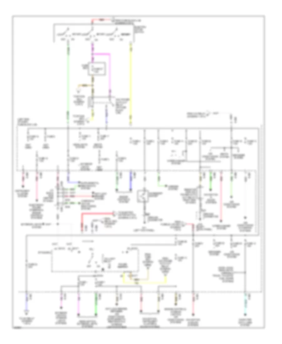
Power Distribution Wiring Diagram (1 of 2) for Mitsubishi i-MiEV SE 2012

List of elements for Power Distribution Wiring Diagram (1 of 2) for Mitsubishi i-MiEV SE 2012:
Power Distribution Wiring Diagram (2 of 2) for Mitsubishi i-MiEV SE 2012
List of elements for Power Distribution Wiring Diagram (2 of 2) for Mitsubishi i-MiEV SE 2012: