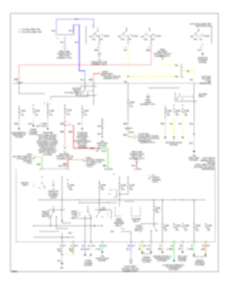
POWER DISTRIBUTION
Power Distribution Wiring Diagram (1 of 3) for Nissan Juke Nismo 2013

List of elements for Power Distribution Wiring Diagram (1 of 3) for Nissan Juke Nismo 2013:
- (on battery (+) post) fuse, fusible link & relay box
- Acc rly cont
- Accessory relay
- Air conditioning, door locks, anti-theft, computer data lines, warning & instrument cluster systems
- Anti-lock brakes system
- Bat (f/l)
- Battery
- Battery terminal w/ fusible link
- Bcm
- Cooling fans system
- E105
- E106
- Electronic power steering system
- Engine controls system
- Exterior lights system
- From ignition switch (diagram 2 of 3)
- Fuse 10a
- Fuse 15a
- Fuse 20a
- Fuse block (j/b) (left end of dash)
- Fusible link a 250a
- Fusible link b 100a
- Fusible link c 80a
- Fusible link d 80a
- Fusible link e 80a
- Fusible link g 40a
- Fusible link h 40a
- Fusible link i 50a
- Fusible link j 50a
- Fusible link k 30a
- Fusible link m 60a
- Instrument cluster system
- Instrument cluster, mirrors, navigation & sound systems
- Instrument cluster, mirrors, navigation, sound & body computer systems
- M35 (right end of dash)
- M66
- M69
- M70
- M76 (left side of dash)
- M77
- M78
- Navigation & sound systems
- Nca
- Pnk
- Pnk e105
- Power socket
- Red
- Seats system
- Starting/ charging & horns systems
- Starting/ charging system
- Starting/ charging, door locks & anti-theft systems
- Stop lp sw 2
- To bcm (body control module) (diagram 3 of 3)
- To blower relay (diagram 2 of 3)
- To fuse holder (diagram 3 of 3)
- To ignition switch (diagram 2 of 3)
- To ipdm e/r (intelligent power distribution module engine room) (diagram 2 of 3)
- To push button ignition switch (diagram 3 of 3)
- Transmissions system
- W/ daytime running light system
- W/ intelligent key
- W/o intelligent key
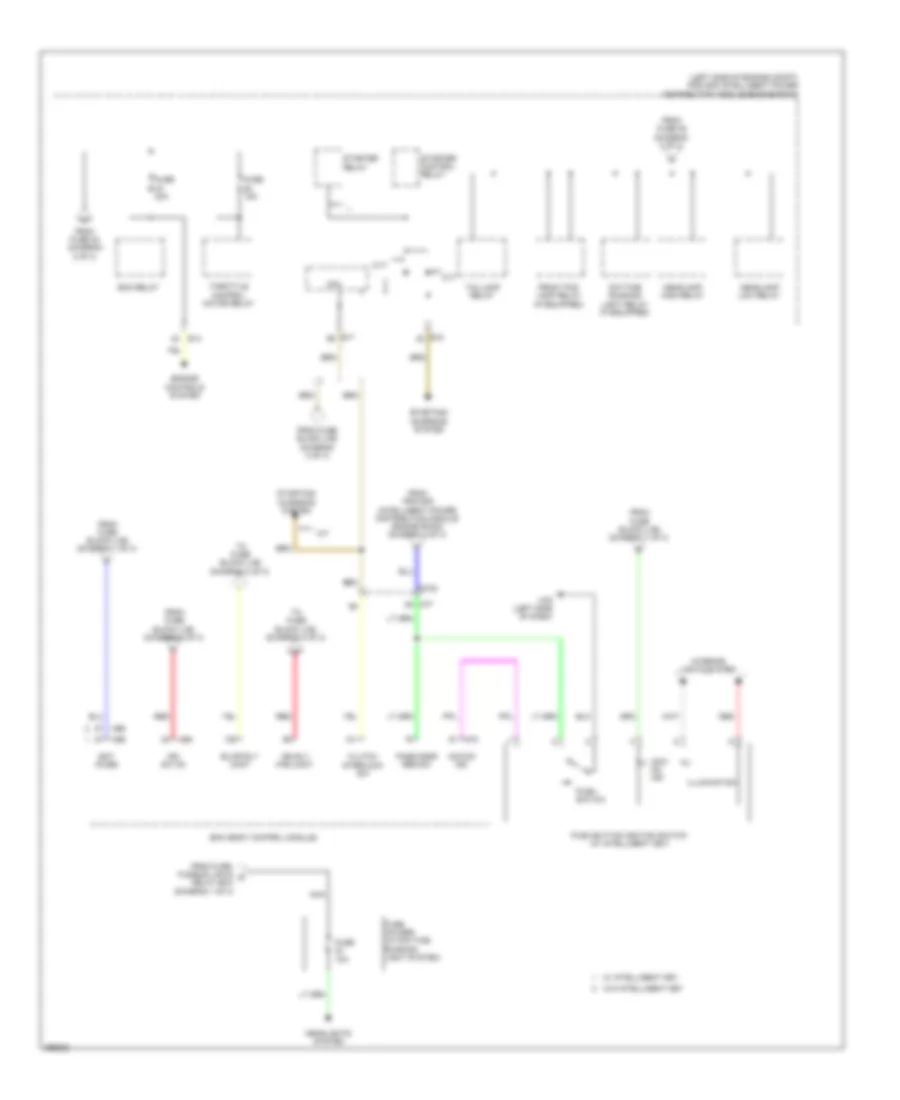
Power Distribution Wiring Diagram (2 of 3) for Nissan Juke Nismo 2013
List of elements for Power Distribution Wiring Diagram (2 of 3) for Nissan Juke Nismo 2013:
- (diagram 3 of 3)
- (left end of dash) fuse block (j/b)
- (left side of engine compt) ipdm e/r (intelligent power distribution module engine room)
- (w/o intelligent key) ignition switch
- A/c relay
- Acc
- Air conditioning system
- Anti-lock brakes system
- Blower relay
- Computer data lines, sound, air conditioning, anti-lock brakes, instrument cluster, electronic power steering, seats, transmissions, cruise control & shift interlock systems
- Cpu
- Cruise control & transmissions systems
- E10
- E105
- E11
- E12
- E13
- E14
- E15
- E17
- E21
- Engine controls system
- Engine controls systems
- From battery terminal b w/ fusible link (diagram 1 of 3)
- From battery terminal w/ fusible link (diagram 1 of 3)
- From bcm (body control module (diagram 3 of 3)
- From bcm (body control module) (diagram 3 of 3)
- From fuse 9 (diagram 1 of 3)
- From fuse, fusible link & relay box (diagram 1 of 3)
- Front wiper hi/lo relay
- Front wiper relay
- Fuel pump relay
- Fuse 10a
- Fuse 15a
- Fuse 30a
- Ignition relay
- Ignition relay (w/ intelligent key)
- M35 (right end of dash)
- M77
- Off
- On acc
- Pnk
- Rear window defogger relay
- Red
- Start
- Starter relay
- Starting/ charging system
- Starting/ charging, instrument cluster, transmissions & anti-lock brakes systems
- Starting/charging & transmissions systems
- To bcm (body control module) (diagram 3 of 3)
- To fuse 43 (diagram 3 of 3)
- To fuse block (j/b) (diagram 1 of 3)
- To headlamp low relay (diagram 3 of 3)
- To ipdm e/r (intelligent power distribution module engine room)
- W/ intelligent key
- W/o intelligent key
- Wiper/ washer system
Power Distribution Wiring Diagram (3 of 3) for Nissan Juke Nismo 2013
List of elements for Power Distribution Wiring Diagram (3 of 3) for Nissan Juke Nismo 2013:
- (left side of engine compt) ipdm e/r (intelligent power distribution module engine room)
- Acc/ on ind
- Acc/on ind
- Bat (fuse)
- Bcm (body control module)
- Blwr rly cont
- Clutch interlock sw
- Cpu
- Cvt
- Daytime running light relay (if equipped)
- E105
- E14
- E15
- E17
- Ecm relay
- Engine controls system
- From fuse 42 (diagram 2 of 3)
- From fuse 46 (diagram 2 of 3)
- From fuse block (j/b) (diagram 1 of 3)
- From fuse block (j/b) (diagram 2 of 3)
- From fuse, fusible link & c relay box (diagram 1 of 3)
- From ipdm e/r (intelligent power distribution module engine room) (diagram 2 of 3)
- Front fog lamp relay (if equipped)
- Fuse 10a
- Fuse 15a
- Fuse 20a
- Fuse holder (w/ daytime running light system)
- Headlamp high relay
- Headlamp low relay
- Headlights system
- Ign rly (f/b) cont
- Ign sw on
- Illumination
- Interior lights system
- M/t
- M65
- M66
- M69
- M70
- M76 (left side of dash)
- M77
- Nca
- Pass door req sw
- Push button ignition switch (w/ intelligent key)
- Push switch
- Red
- Starter control relay
- Starter relay
- Starting/ charging system
- Taillamp relay
- Throttle control motor relay
- To fuse block (j/b) (diagram 2 of 3)
- W/ intelligent key
- W/o intelligent key