SHIFT INTERLOCK
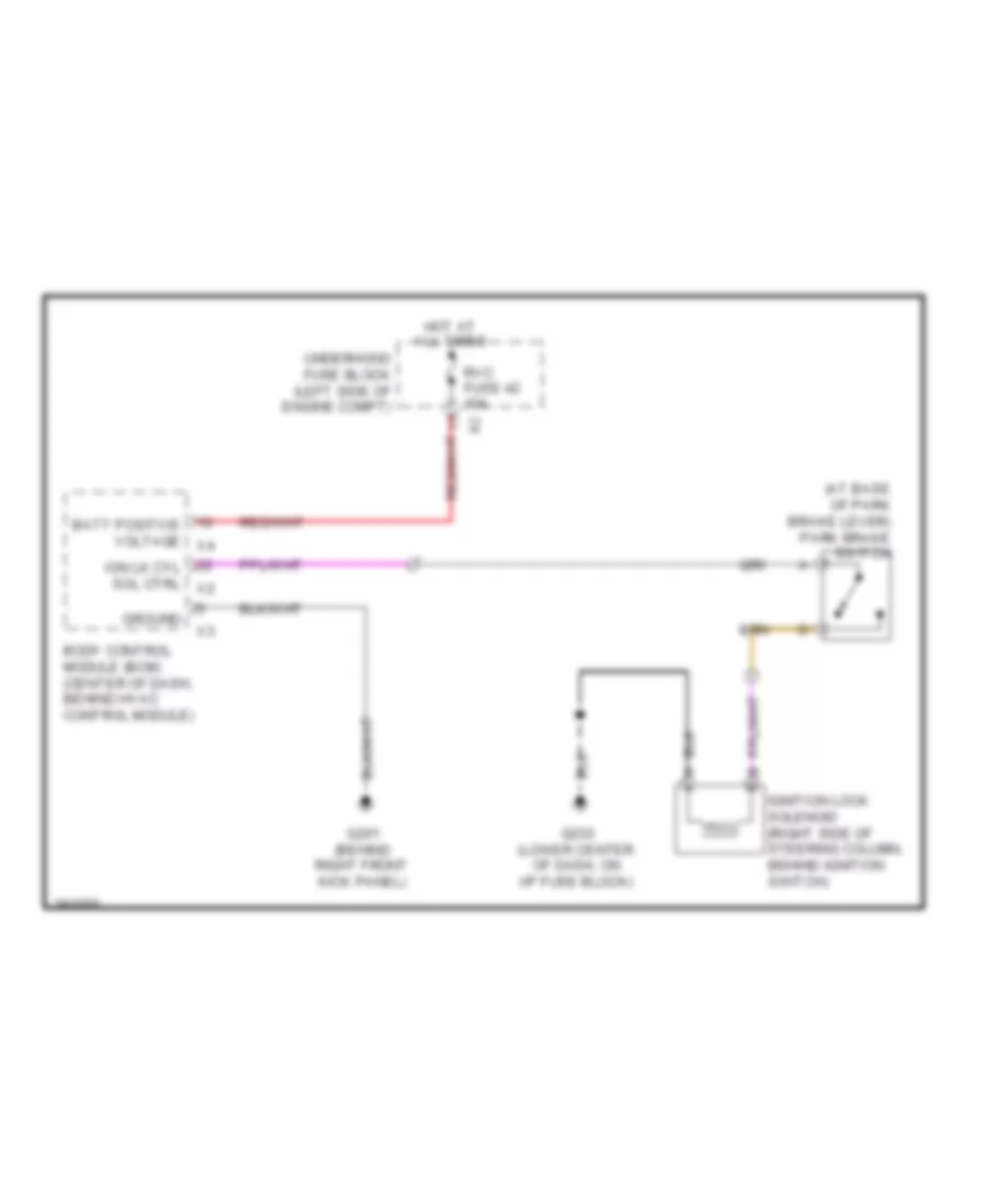
Ignition Lock Solenoid Wiring Diagram for Suzuki XL7 Premium 2008
List of elements for Ignition Lock Solenoid Wiring Diagram for Suzuki XL7 Premium 2008:
11
- (at base of park brake lever) park brake switch
- Batt positive voltage x4
- Body control module (bcm) (center of dash, behind hvac control module)
- G201 (behind right front kick panel)
- G203 (lower center of dash, on i/p fuse block)
- Ground
- Hot at all times
- Ign lk cyl sol ctrl x2
- Ignition lock solenoid (right side of steering column, behind ignition switch)
- Rvc fuse 42 10a
- Underhood fuse block (left side of engine compt)
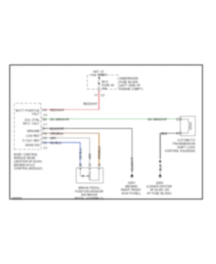
Shift Interlock Wiring Diagram for Suzuki XL7 Premium 2008
List of elements for Shift Interlock Wiring Diagram for Suzuki XL7 Premium 2008:
14
- 5 volt ref
- Automatic transmission shift lock control solenoid
- Batt positive volt x4
- Body control module (bcm) (center of dash, behind hvac control module)
- Brake pedal position sensor (on brake pedal assembly)
- G201 (behind right front kick panel)
- G203 (lower center of dash, on i/p fuse block)
- Ground
- Hot at all times
- Low ref
- Rvc fuse 42 10a
- Sens sig
- Sol ctrl sply volt x1
- Underhood fuse block (left side of engine compt)