
SHIFT INTERLOCKS
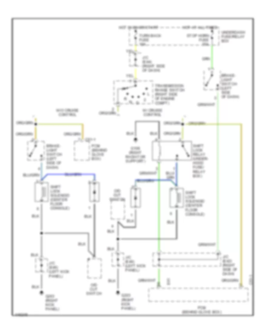
Shift Interlock Wiring Diagram for Suzuki XL-7 2001
List of elements for Shift Interlock Wiring Diagram for Suzuki XL-7 2001:
AIR CONDITIONINGCOMPUTER DATA LINESANTI-LOCK BRAKESENGINE PERFORMANCECRUISE CONTROLEXTERIOR LIGHTSGROUND DISTRIBUTIONHEADLIGHTSINTERIOR LIGHTSINSTRUMENT CLUSTERDEFOGGERSHORNPOWER TOP/SUNROOFPOWER DISTRIBUTIONRADIOPOWER DOOR LOCKSPOWER MIRRORSSHIFT INTERLOCKSPOWER WINDOWSSUPPLEMENTAL RESTRAINTSSTARTING/CHARGINGTRANSMISSIONWARNING SYSTEMSWIPER/WASHER