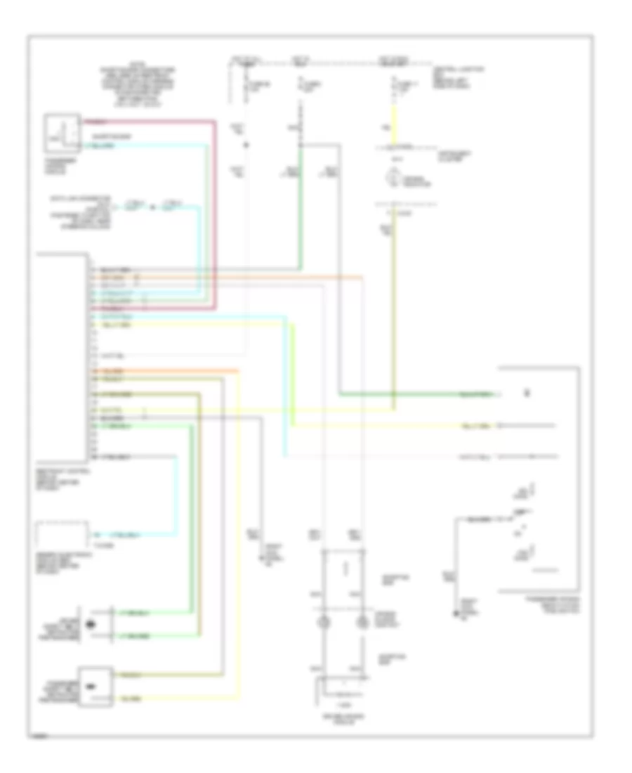
SUPPLEMENTAL RESTRAINTS
Supplemental Restraint Wiring Diagram for Mazda B2300 2002
List of elements for Supplemental Restraint Wiring Diagram for Mazda B2300 2002:
- (right kick panel) g8
- 1 ohm
- Air bag indicator
- Air bag sliding contact
- C-216
- Central junction box (behind left side of dash)
- Data link connector (dlc) (partial) (fastened to bottom of dash, near steering column)
- Driver air bag module
- Driver safety belt retractor pretensioner
- Fuse 11 7.5a
- Fuse 2 20a
- Fuse 26 10a
- Generic electronic module (gem) (behind center of dash)
- Hot at all times
- Hot in run
- Hot in run or start
- Instrument cluster
- Nca
- Note: shorting bar connectors are used on restraint control module harness connector when module is disconnected between pins 3 & 4, 6 & 7, 20 & 21
- Off
- Ohm
- Ohms
- Passenger air bag deactivation (pad) switch
- Passenger air bag module
- Passenger safety belt retractor pretensioner
- Restraint control module (behind center of dash)
- Shorting bar
- T-2100b
 English