SUPPLEMENTAL RESTRAINTS
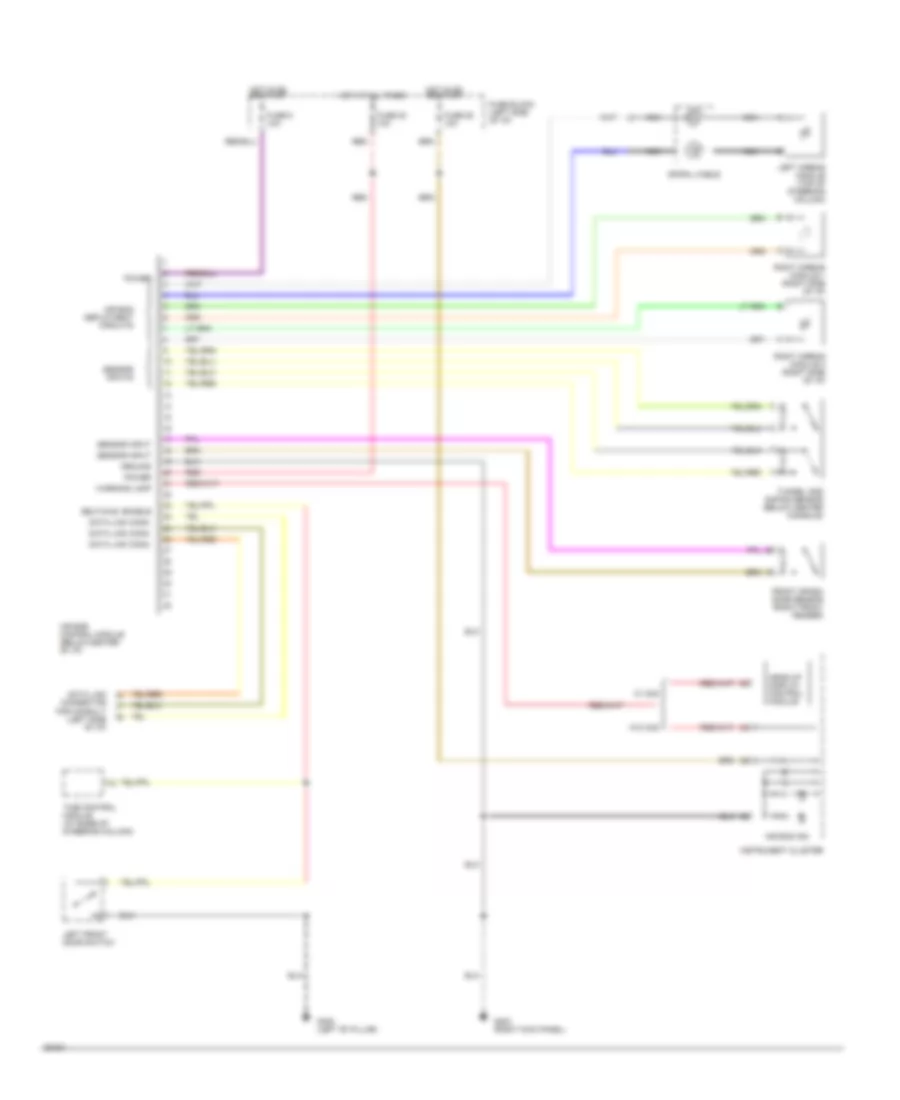
Supplemental Restraint Wiring Diagram for Nissan Altima GLE 1994
List of elements for Supplemental Restraint Wiring Diagram for Nissan Altima GLE 1994:
- Air bag control module (below center of i/p)
- Air bag deployment circuits
- Air bag ind.
- Data link conn.
- Data link connector for consult (left side of i/p)
- Front crash zone sensor (right front fender)
- Fuse 20 10a
- Fuse 25 10a
- Fuse 5 10a
- Fuse block (left side of i/p)
- G203 (right kick panel)
- G308 (left "b" pillar)
- Ground
- Head-up display control module
- Hot at all times
- Hot in on or start
- Instrument cluster
- Left airbag module (top of steering column)
- Left front door switch
- Nca
- Power
- Red
- Right airbag module 1 (right side of i/p)
- Right airbag module 2 (right side of i/p)
- Self diag. enable
- Sensor input
- Sensor inputs
- Spiral cable
- Time control module (at base of steering column)
- Tunnel and safing sensor (below center console)
- W/ hud
- W/o hud
- Warning lamp
 English