SUPPLEMENTAL RESTRAINTS
Supplemental Restraints Wiring Diagram for Suzuki Grand Vitara 2003
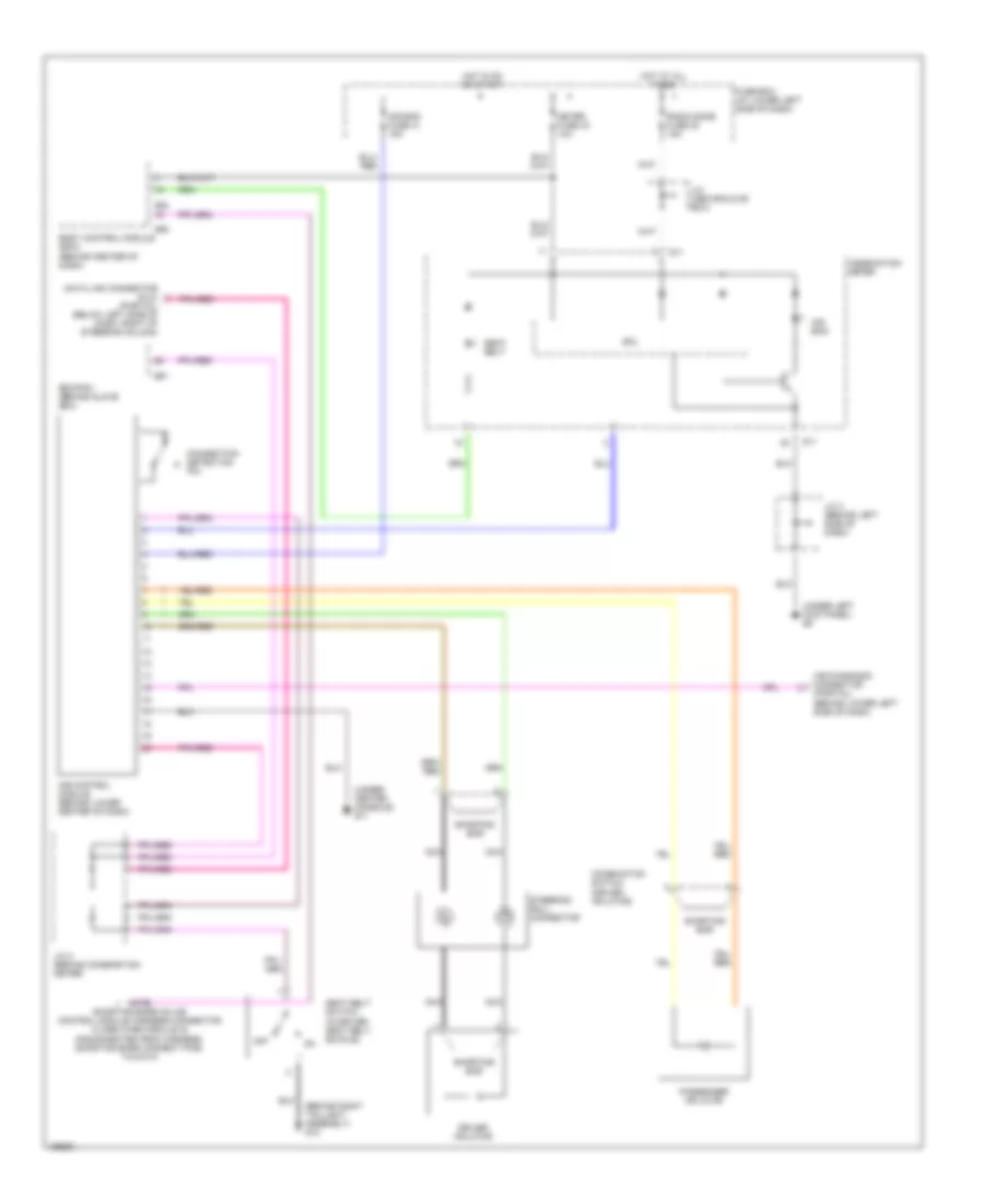
List of elements for Supplemental Restraints Wiring Diagram for Suzuki Grand Vitara 2003:
- (behind right taillight assembly) g12
- (under center console) g11
- (under left kick panel) g9
- A/b control module (behind lower center of dash)
- A/b diagnosis connector (partial) (behind lower left side of dash)
- Air bag
- Air bag fuse 41 15a
- Body control module (bcm) (behind center of dash)
- Combination meter
- Combination switch (driver inflator)
- Connection detection pin
- Cpu
- Data link connector (dlc) (partial) (below left side of dash, right of steering column)
- Driver inflator
- E61
- Ecm/pcm (behind glove box)
- Fuse box (at lower left side of dash)
- G11
- G54
- G55
- Hot at all times
- Hot in on or start
- J/c (above glove box)
- J/c 2 (behind combination meter)
- J/c 3 (behind left side of dash)
- Meter fuse 43 10a
- Nca
- Note: shorting bars on a/b control module harness connector close when module is disconnected from harness. shorting bars connect pins: 7-8 & 9-10
- Off
- Passenger inflator
- Radio dome fuse 35 15a
- Seat belt
- Seat belt switch (in driver seat belt buckle)
- Shorting bar
- Steering roll connector
 English