TRANSMISSION
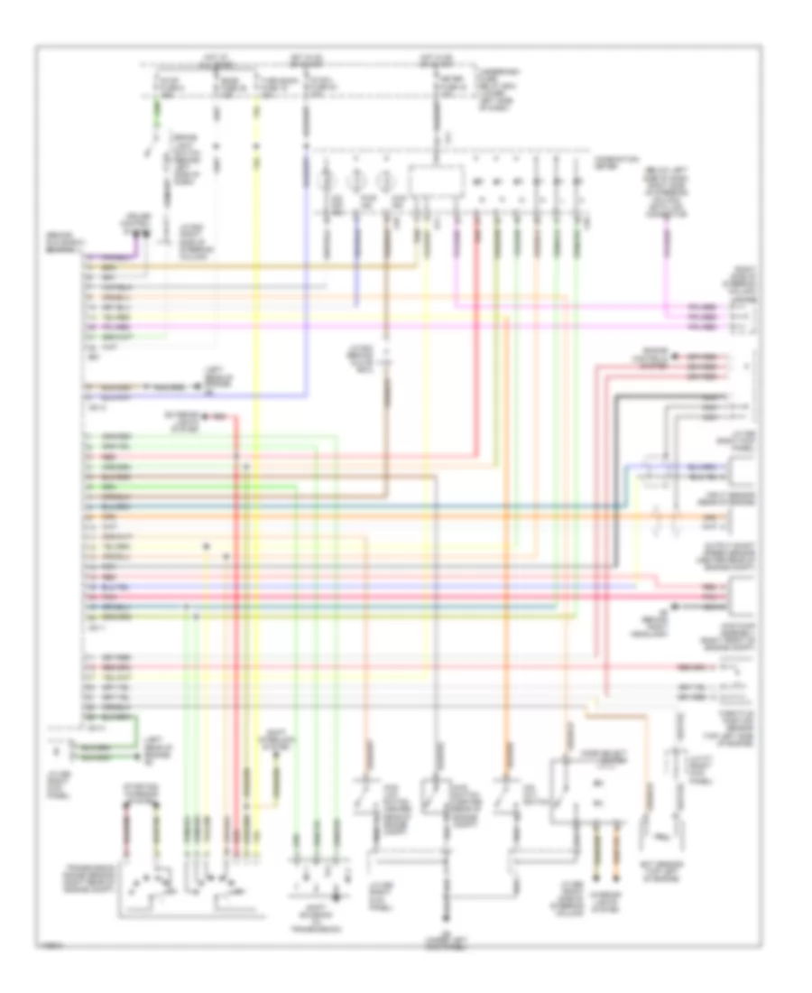
A/T Wiring Diagram for Suzuki Grand Vitara 2003
List of elements for A/T Wiring Diagram for Suzuki Grand Vitara 2003:
- (behind glove box) ecm/pcm
- (below left side of dash, right side of steering column) data link connector
- (left rear of engine) g5
- (right side of steering column) j/c g16
- 4wd ind
- 4wd low switch (center rear of engine compt)
- 4wd pump assembly (right front of engine compt)
- 4wd switch (center rear of engine compt)
- Brake light switch (behind left side of dash)
- C51-1
- C51-2
- C51-3
- Combination meter
- Cruise control system
- Dome fuse 35 15a
- E61
- Ect sensor (top left of engine)
- Engine controls system
- Exterior lights system
- G10
- G11
- G8 (behind right headlamp)
- G9 (under left kick panel)
- Hot at all times
- Hot in on or start
- Ig coil fuse 40 20a
- Input sensor (rear of engine)
- Interior lights system
- J/c c66 (right kick panel)
- J/c c69 (right kick panel)
- J/c c71 (right kick panel)
- J/c e42 (right side of steering column)
- J/c e43 (behind glove box)
- J/c g29 (right side of steering column)
- Meter fuse 43 10a
- Mode select switch
- N r
- Nca
- No 1
- No 2
- O/d cut switch
- O/d off ind
- Output shaft speed sensor (center rear of engine compt)
- Pnk
- Pwr ind
- Red
- Shift interlock system
- Shift solenoid (in tramsmission)
- Starting/ charging system
- Stop fuse 9 15a
- Tcc
- Throttle position sensor (top left side of engine)
- Transmission range sensor (right rear of engine compt)
- Turn back fuse 19 10a
- Underdash fuse/ relay box (lower left side of dash)
 English