TRANSMISSION
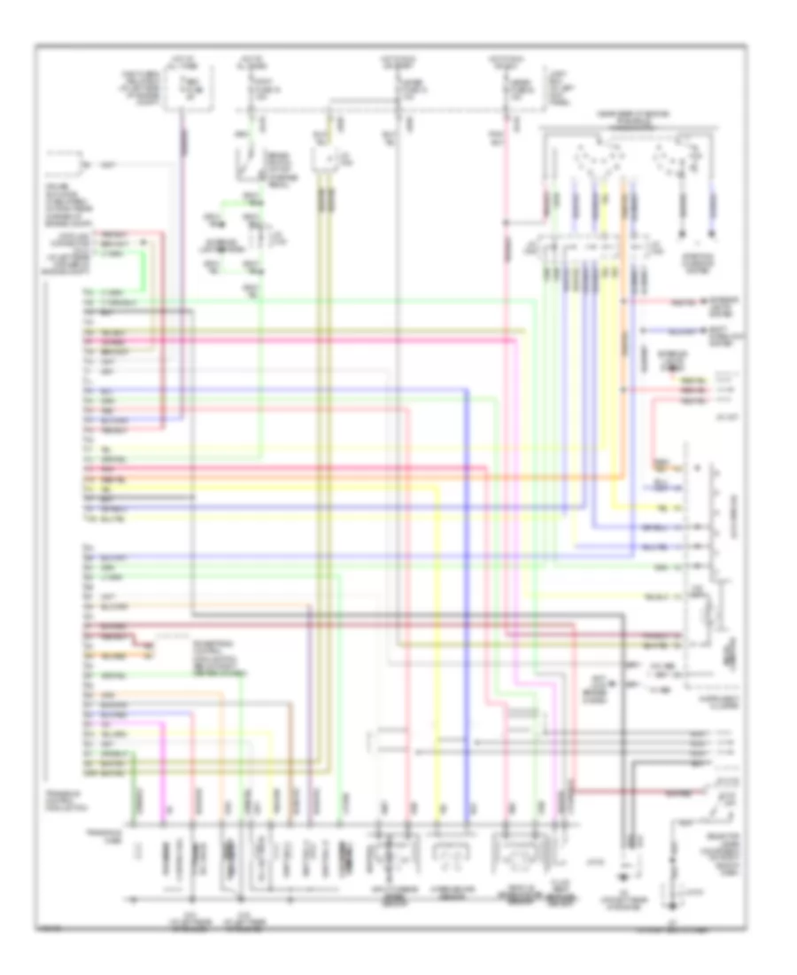
A/T Wiring Diagram for Mazda MPV LX 2004
List of elements for A/T Wiring Diagram for Mazda MPV LX 2004:
- (lcd display)
- (near rear of engine) transaxle range switch
- 1aa
- 2-4 brake sol valve
- 2aa
- Anti- lock brakes system
- Brake switch (at top of brake pedal)
- Control sol
- Cruise actuator (if equipped) (at right rear corner of engine compt)
- Data link connector (dlc) (at left rear corner of engine compt)
- Eec fuse 5a
- Exterior lights system
- Fluid temp- erature sensor
- G15 (at left rear of engine)
- G3 (at right rear of engine)
- G7 (at right end of dash)
- High clutch
- Hot at all times
- Hot in run or acc
- Hot in run or start
- Input/turbine speed sensor
- Instrument cluster
- Intermediate sensor
- J/c x-08
- J/c x-09
- J/c x-19
- J/c x-27
- J/c x-28
- J/c-02
- J/c-03
- Jb-09
- Jb-10
- Joint box (at left kick panel)
- Main fuse & relay box (at left side of engine compt)
- Meter fuse 18 10a
- Meter fuse 22 15a
- Micro- computer
- Nca
- Neutral
- O/d off
- Pnk
- Powertrain control module (pcm) (below right center of dash)
- Pressure
- Red
- Selector lever component (on right side of dash)
- Shift interlock system
- Shift sol a
- Shift sol b
- Shift sol c
- Sol valve
- Starting/ charging system
- Stop fuse 19 15a
- Tcc sol valve
- Timing sol reduction
- Transaxle case
- Transaxle control module (tcm)
- Valve
- Valve shift sol
- Vehicle speedometer sensor
- W/ abs
- W/o abs
 English