TRANSMISSION
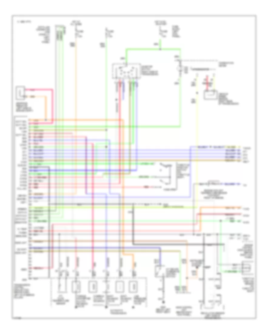
A/T Wiring Diagram for Nissan 240SX 1998
List of elements for A/T Wiring Diagram for Nissan 240SX 1998:
- 1 pos
- 1995 vftc c
- 2 pos
- A/t device (overdrive control switch)
- A/t fluid temperature sensor
- All times
- Ascd control unit (behind right kick panel)
- Ascd unit
- Atck
- Automatic transmission
- Avcc
- Closed
- Cluster system
- Combination meter
- D pos
- Data clk
- Data in
- Data link connector (for consult) (left kick panel)
- Data out
- Dropping resistor (left side of engine compt)
- Dt1
- Dt2
- Dt3
- Duty sol
- Eng rev
- Engine control module (ecm) (behind right kick panel)
- Engine coolant temperature sensor (top right front of engine)
- Fl temp
- Full sw
- Fuse 7.5a
- Fuse block (left kick panel)
- G125 (front of engine)
- G300 (below left front seat)
- Gnd
- Gnd a
- Hot at
- Hot in on or start
- Idle sw
- Inhibitor switch (right side of transmission)
- Instrument
- Line pressure solenoid valve
- Mem b/u
- N pos
- N sig
- Nca
- Neut
- O/d off ind
- Obd2
- Od cont
- Od off
- Overrun clutch solenoid
- Ovr/c
- Pnk
- R pos
- Red
- Revolution sensor (left side of transmission)
- Sens gnd
- Sens pwr
- Shift solenoid valve a
- Shift solenoid valve b
- Speedo
- Speedometer
- Ssa
- Ssb
- Tacho
- Th/sen
- Throttle position sensor (on throttle body)
- Throttle position switch (on throttle body)
- Torque converter clutch solenoid valve
- Transmission control module (tcm) (behind dash, left of steering column)
- Tv01
- Tvoo
- Vehicle speed sensor (right rear of transmission)
- Vign
- Vsp-1
- Wide open
 English