WARNING SYSTEMS
Chime Wiring Diagram for Mitsubishi Eclipse Spyder GT 2008

List of elements for Chime Wiring Diagram for Mitsubishi Eclipse Spyder GT 2008:
- (behind left side of dash) joint connector 2
- (under floor console, near parking brake lever) g17
- C203
- C208
- C215
- C217
- C218
- C219
- Column switch
- Combination meter
- Computer data lines system
- Cpu
- Door ind
- Driver's seat belt switch (in driver's seat belt buckle)
- Engine compartment relay box (left side of engine compt)
- Etacs ecu
- Fuse 2 7.5a
- Fuse 22 10a
- G17 (under floor console, near parking brake lever)
- G3 (under center of dash)
- G4 (behind left side of dash)
- Head/tail lamp on
- Hot at all times
- Hot in run or start
- Joint connector 2 (behind left side of dash)
- Junction block (under left end of dash)
- Key reminder switch (in steering column)
- Left door switch (at left "b" pillar)
- Nca
- Seat belt ind
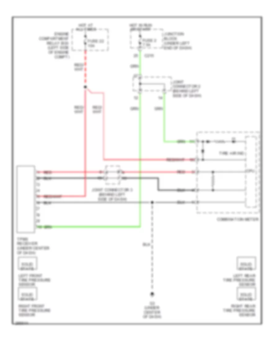
Tire Pressure Monitoring Wiring Diagram for Mitsubishi Eclipse Spyder GT 2008
List of elements for Tire Pressure Monitoring Wiring Diagram for Mitsubishi Eclipse Spyder GT 2008:
- C215
- Combination meter
- Cpu
- Engine compartment relay box (left side of engine compt)
- Fuse 2 7.5a
- Fuse 22 10a
- G3 (under center of dash)
- Hot at all times
- Hot in run or start
- Joint connector 2 (behind left side of dash)
- Joint connector 3 (behind left side of dash)
- Junction block (under left end of dash)
- Left front tire pressure sensor
- Left rear tire pressure sensor
- Red
- Right front tire pressure sensor
- Right rear tire pressure sensor
- Solid state
- Tire air ind
- Tpms receiver (under center of dash)