AIR CONDITIONING
Air Conditioning Wiring Diagrams for Chevrolet Caprice Classic 1996
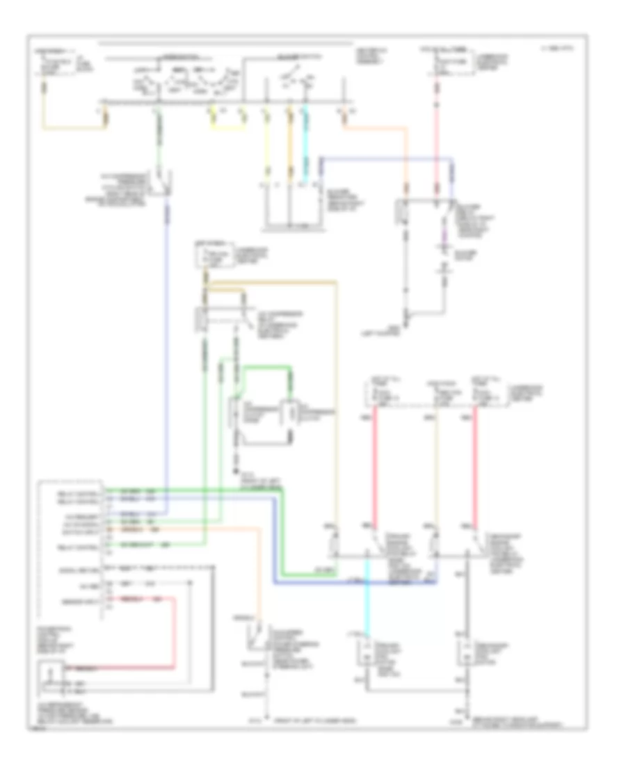
List of elements for Air Conditioning Wiring Diagrams for Chevrolet Caprice Classic 1996:
- (behind right headlamp attached to radiator support)
- (front of left
- (front of left cylinder head)
- +5v ref
- A/c compressor clutch
- A/c compressor clutch diode
- A/c compressor pressure cycling switch (right rear of engine compartment, on accumulator)
- A/c compressor relay (in underhood electrical centera)
- A/c on signal
- A/c refrigerant pressure sensor (in high pressure line, below coolant reservoir)
- A/c request
- Bi-lv
- Blower motor
- Blower relay (below right side of i/p, near right kickpad)
- Blower resistors (behind right side of i/p)
- Blower switch
- C 1995 vftc
- C tan
- Cylinder head)
- Def
- G109
- G112
- G200 (left kickpad)
- Heater-a/c control assembly
- Hot at all times
- Hot in run
- Htr
- Hvac blo fuse 20a
- I/p fuse block
- Idle speed control power steering pressure switch (near power steering unit)
- Max
- Maxi fuse 12 40a
- Maxi fuse 13 40a
- Maxi fuse 60a
- Mode switch
- Nca
- Norm
- Off
- Powertrain control module (behind right side of i/p)
- Pri fan fuse 10a
- Primary coolant fan motor (base and v03)
- Primary engine coolant fan relay (base and v03) (underhood electrical center)
- Red
- Relay control
- Sec fan fuse 10a
- Secondary coolant fan motor
- Secondary engine coolant fan relay (underhood electrical center)
- Sensor input
- Signal return
- Switch input
- Tan
- Underhood electrical center
- Vent
 English