AIR CONDITIONING
Compressor Wiring Diagram for Chevrolet Equinox LT 2005

List of elements for Compressor Wiring Diagram for Chevrolet Equinox LT 2005:
- 5 volt ref
- A tan
- A/c clutch fuse 10a
- A/c clutch relay
- A/c compressor clutch (lower left front of engine)
- A/c diode
- A/c refrigerant pressure sensor (near back of a/c compressor)
- A/c req sig
- A/c request
- A/c switch
- A10
- B11
- Body control module (bcm) (center of dash, behind hvac control module)
- C8 c1
- Can high
- Can low
- Computer data lines system
- D12
- E3 c3
- Evap temp sens
- Evaporator temperature sensor (in engine compt, on expansion valve block)
- F12
- G101 (at left front of engine compt)
- Hot at all times
- Hot in run or start
- Hvac control module (at center of dash)
- Logic
- Low ref
- Powertrain control module (pcm) (in engine compartment, mounted on top of battery cover)
- Rly ctrl
- Sens sig
- Tan
- Under- hood fuse block (left side of engine compt)
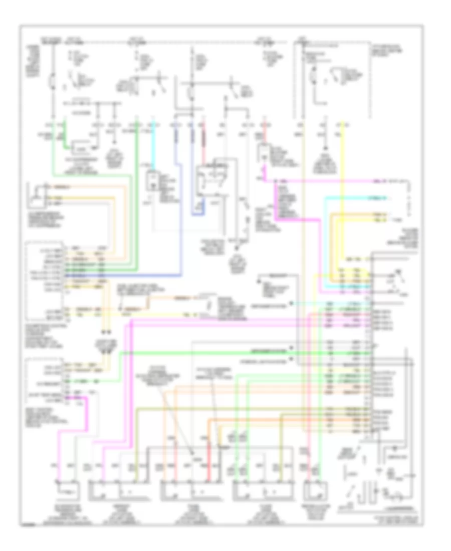
Manual A/C Wiring Diagram for Chevrolet Equinox LT 2005
List of elements for Manual A/C Wiring Diagram for Chevrolet Equinox LT 2005:
- (fuel injector harn, between fuel injector 3 & 4 breakouts)
- (in hvac harness, 25 cm from defroster mode actuator breakout)
- (in hvac harness, 7 cm from breakout to c202)
- 5 volt ref
- 87a
- A/c clutch fuse 10a
- A/c clutch relay
- A/c compressor clutch (lower left front of engine)
- A/c diode
- A/c led
- A/c refrigerant pressure sensor (near back of a/c compressor)
- A/c req sig
- A/c request
- A/c switch
- A10
- A12 c1
- A2 c1
- A2 c3
- A7 c3
- B c5
- B11
- Bcm/hvac fuse 10a
- Blower motor resistor (behind blower motor)
- Blw mtr lo
- Body control module (bcm) (center of dash, behind hvac control module)
- C8 c1
- Can high
- Can low
- Computer data lines system
- Cool fan hi fuse 25a
- Cool fan hi relay
- Cool fan lo fuse 25a
- Cool fan lo relay
- Cooling fan s/p relay (below left headlamp)
- D12
- Def mod a
- Def mod b
- Defog ind
- Defogger system
- Defrost mode actuator (on left side of hvac assembly)
- E3 c3
- Ect sig
- Engine coolant temperature (ect) sensor (lower right side of engine)
- Evap temp sens
- Evaporator temperature sensor (in engine compt, on expansion valve block)
- F12
- Fan hi rly ctrl
- Fan lo rly ctrl
- Floor mode actuator (on left side of hvac assembly)
- Flr mod a
- Flr mod b
- G101 (at left front of engine compt)
- G201 (behind right front kick panel)
- G203 (lower center of dash, on i/p fuse block)
- Gnd
- High
- Hot at all times
- Hot in run
- Hot in run or start
- Hvac blower fuse 40a
- Hvac blower motor (right side of hvac assy)
- Hvac blower relay
- Hvac control module (at center of dash)
- I/p fuse block (behind center of dash)
- Ign
- Illumination
- Interior lights system
- Left cooling fan (behind left side of radiator)
- Logic
- Low ref
- Off
- Pan mod a
- Pan mod b
- Panel mode actuator (on right side of hvac assembly)
- Pos sens
- Pos sig
- Powertrain control module (pcm) (in engine compartment, mounted on top of battery cover)
- Rear defog switch
- Rec dr a
- Rec dr b
- Recirculation actuator (on hvac module)
- Red
- Right cooling fan (behind right side of radiator)
- Rly ctrl
- S104
- S206
- S207
- Sens sig
- Tan
- Under- hood fuse block (left side of engine compt)