AIR CONDITIONING
Compressor Wiring Diagram for Chevrolet Impala 2000

List of elements for Compressor Wiring Diagram for Chevrolet Impala 2000:
- (below left side of dash) data link connector (dlc)
- (engine harn, 6.5 cm from egr valve breakout)
- A/c compressor
- A/c compressor clutch relay (in engine harness wiring junction block)
- A/c compressor diode
- A/c request
- A/c rly coil fuse 10a
- A/c rly fuse 10a
- Body control module (behind left side of dash)
- Class 2 serial data
- E11
- Engine harness wiring junction block (bottom)
- Engine harness wiring junction block (top)
- F11
- G114 (lower left rear of engine)
- Heater & a/c control
- Hot at all times
- Hot in on
- Nca
- Pnk
- Powertrain control module (in air cleaner box)
- Relay control
- Splice pack sp205 (next to left i/p accessory wiring junction block)
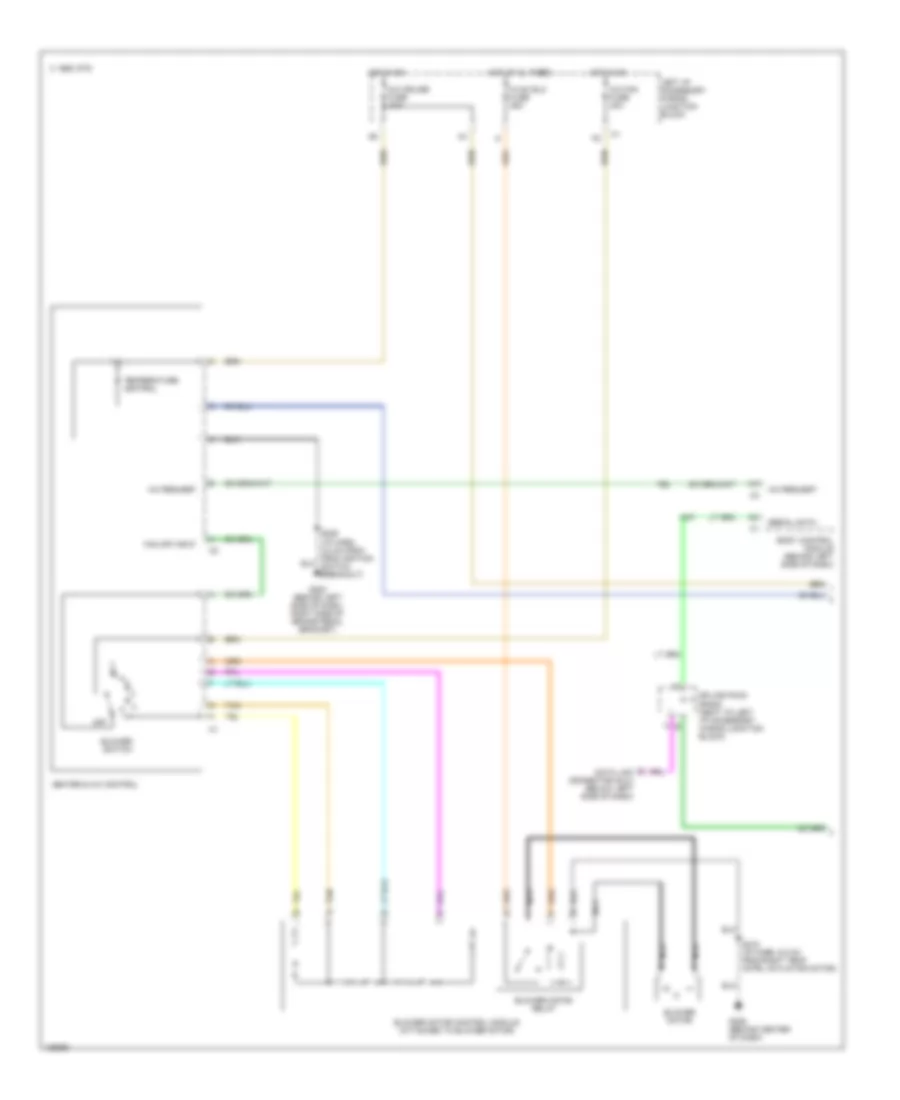
Manual A/C Wiring Diagram, Base (1 of 2) for Chevrolet Impala 2000
List of elements for Manual A/C Wiring Diagram, Base (1 of 2) for Chevrolet Impala 2000:
- A/c cruise fuse 10a
- A/c fan fuse 20a
- A/c request
- Blower motor
- Blower motor control module (attached to blower motor)
- Blower motor relay
- Blower switch
- Body control module (behind left side of dash)
- C 1995 vftc
- Data link connector (dlc) (below left side of dash)
- Fan off input
- G202 (behind left side of dash, right side of brake pedal bracket)
- G206 (behind center of dash)
- Heater & a/c control
- Hot at al times
- Hot in on
- Hvac blo fuse 25a
- Left i/p accessory wiring junction block
- Nca
- Off
- S216 (i/p harn, 6.5 cm from right temp cntrl actuator motor)
- Serial data
- Splice pack sp205 (next to left i/p accessory wiring junction block)
- Tan
- Temperature control
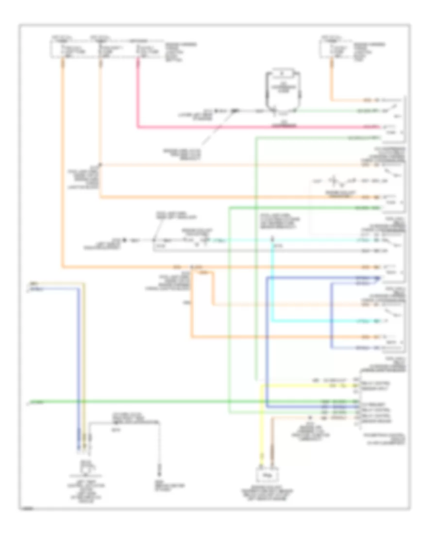
Manual A/C Wiring Diagram, Base (2 of 2) for Chevrolet Impala 2000
List of elements for Manual A/C Wiring Diagram, Base (2 of 2) for Chevrolet Impala 2000:
- (engine harn, 6.5 cm from egr valve breakout)
- (fwd lamp harn, 31.5 cm from outside air temperature sensor breakout)
- (fwd lamp harn, near left headlamp)
- (i/p harn, 6.5 cm from right temp cntrl actuator motor)
- A/c compressor
- A/c compressor clutch relay (in engine harness wiring junction block)
- A/c compressor diode
- A/c request
- A/c rly coil fuse 10a
- A/c rly fuse 10a
- B10
- C10
- Cool fan 1 relay (in engine harness wiring junction block)
- Cool fan 2 relay (in engine harness wiring junction block)
- Cool fan 3 relay (in engine harness wiring junction block)
- E11
- Engine coolant fan motor 1
- Engine coolant fan motor 2
- Engine coolant temperature (ect) sensor (below coolant outlet, left rear of engine)
- Engine harness wiring junction block (bottom)
- Engine harness wiring junction block (top)
- F11
- Fan 2 & 3 cont fuse 25a
- Fan cont 1 fuse 25a
- G108 (left side of radiator support)
- G114 (lower left rear of engine)
- G206 (behind center of dash)
- Hot at all times
- Hot in on
- Left temp control actuator motor (left side of heater & a/c module)
- Nca
- Pnk
- Powertrain control module (in air cleaner box)
- Relay control
- S121 (engine jpr harness, 2 cm from fuel injector 3 breakout)
- S132 (fwd lamp harn, inside top of engine harness wiring junction block)
- S148
- S158
- S175
- S179 (fwd lamp harn, inside top of engine harn wiring junction block)
- S216
- Sensor ground
- Sensor input
- Solid state
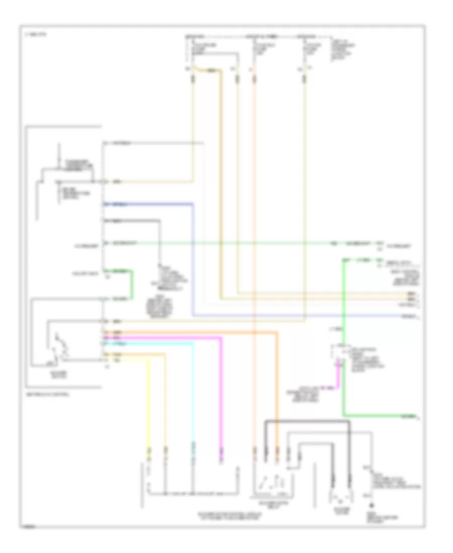
Manual A/C Wiring Diagram, Dual Zone A/C (1 of 2) for Chevrolet Impala 2000
List of elements for Manual A/C Wiring Diagram, Dual Zone A/C (1 of 2) for Chevrolet Impala 2000:
- A/c cruise fuse 10a
- A/c fan fuse 20a
- A/c request
- Blower motor
- Blower motor control module (attached to blower motor)
- Blower motor relay
- Blower switch
- Body control module (behind left side of dash)
- C 1995 vftc
- Data link connector (dlc) (below left side of dash)
- Driver temperature control
- Fan off input
- G202 (behind left side of dash, right side of brake pedal bracket)
- G206 (behind center of dash)
- Heater & a/c control
- Hot at al times
- Hot in on
- Hvac blo fuse 25a
- Left i/p accessory wiring junction block
- Nca
- Off
- Passenger temperature control
- S216 (i/p harn, 6.5 cm from right temp cntrl actuator motor)
- Serial data
- Splice pack sp205 (next to left i/p accessory wiring junction block)
- Tan
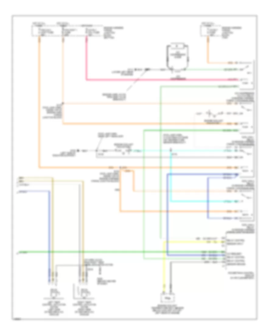
Manual A/C Wiring Diagram, Dual Zone A/C (2 of 2) for Chevrolet Impala 2000
List of elements for Manual A/C Wiring Diagram, Dual Zone A/C (2 of 2) for Chevrolet Impala 2000:
- (engine harn, 6.5 cm from egr valve breakout)
- (fwd lamp harn, 31.5 cm from outside air temperature sensor breakout)
- (fwd lamp harn, near left headlamp)
- (i/p harn, 6.5 cm from right temp cntrl actuator motor)
- A/c compressor
- A/c compressor clutch relay (in engine harness wiring junction block)
- A/c compressor diode
- A/c request
- A/c rly coil fuse 10a
- A/c rly fuse 10a
- B10
- C10
- Cool fan 1 relay (in engine harness wiring junction block)
- Cool fan 2 relay (in engine harness wiring junction block)
- Cool fan 3 relay (in engine harness wiring junction block)
- E11
- Engine coolant fan motor 1
- Engine coolant fan motor 2
- Engine coolant temperature (ect) sensor (below coolant outlet, left rear of engine)
- Engine harness wiring junction block (bottom)
- Engine harness wiring junction block (top)
- F11
- Fan 2 & 3 cont fuse 25a
- Fan cont 1 fuse 25a
- G108 (left side of radiator support)
- G114 (lower left rear of engine)
- G206 (behind center of dash)
- Hot at all times
- Hot in on
- Left temp control actuator motor (left side of heater & a/c module)
- Nca
- Pnk
- Powertrain control module (in air cleaner box)
- Relay control
- Right temp control actuator motor (right side of heater & a/c module)
- S132 (fwd lamp harn, inside top of engine harness wiring junction block)
- S148
- S158
- S175
- S179 (fwd lamp harn, inside top of engine harn wiring junction block)
- S216
- Sensor ground
- Sensor input
- Solid state