POWER DISTRIBUTION
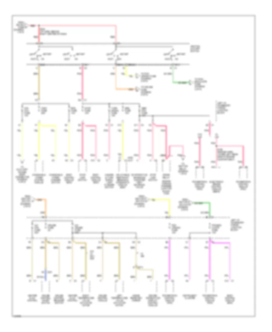
Power Distribution Wiring Diagram (1 of 5) for Chevrolet Impala 2000

List of elements for Power Distribution Wiring Diagram (1 of 5) for Chevrolet Impala 2000:
- (i/p harn, behind red
- Audio power booster (uq3)
- B10
- Battery
- Cd player (uq3)
- Circuit breaker 1 30a
- Circuit breaker 2 30a (seo)
- Circuit breaker 3 50a
- Cooling fans fuse 60a
- D11
- Electronic brake control module (ebcm)
- Engine wiring harness junction block (bottom)
- Engine wiring harness junction block (top)
- F nca
- F10
- F11
- From crank o relay (diagram 2 of 5)
- Fuse 15a
- Fuse block (seo) (rpo 9c1/9c6)
- Fusible link (5 ga-rust)
- G202 (behind left side of dash, on right side of brake pedal bracket)
- Generator
- Htd mir fuse 10a
- Ign sw fuse 60a
- Ignition relay
- Left i/p accessory wiring junction block
- Left i/p fuse 60a
- Left outside rearview mirror
- Left spot lamp
- Nca
- Pnk
- Radio
- Radio antenna module
- Radio fuse 15a
- Rear defog circuit breaker 30a
- Rear defog relay
- Red
- Remote battery stud
- Right i/p 1 fuse 60a
- Right i/p 2 fuse 60a
- Right i/p accessory wiring junction block
- Right of dash, near bcm breakout) s244
- Right outside rearview mirror
- Right spot lamp
- S174
- Starter motor
- To air pmp rly fuse (diagram 3 of 5)
- To engine wiring harness junction block (top) (diagram 3 of 5)
- To engine wiring harness junction block (top) (diagram 5 of 5)
- To fan 1 cont fuse (diagram 3 of 5)
- To ignition switch (diagram 2 of 5)
- To left i/p accessory wiring junction block (diagram 3 of 5)
- To right i/p accessory wiring junction block (diagram 4 of 5)
- To right i/p accessory wiring junction block (diagram 5 of 5)
- To splice s177 (diagram 3 of 5)
- U/hood fuse 60a
- W/ nc1
- Wiring harness junction block (seo) (9c1/9c6)
Power Distribution Wiring Diagram (2 of 5) for Chevrolet Impala 2000
List of elements for Power Distribution Wiring Diagram (2 of 5) for Chevrolet Impala 2000:
- (aj7)
- (ak5)
- A/c cruise fuse 10a
- A/c fan fuse 20a
- A10
- A11
- A12
- Abs/ pcm fuse 10a
- Acc
- Accy
- Bcm fuse 10a
- Body control module (bcm)
- C201
- C373
- Cig/ aux fuse 10a
- Crank
- Crank relay
- Cruise control module
- Cruise control on/off switch
- Cruise control release switch
- Cruise fuse 2a
- D11
- Driver information display control module
- Electronic brake control module (ebcm)
- Engine wirning harness junction block (top)
- Evaporative emissions canister vent solenoid valve
- F10
- From ign sw fuse (diagram 1 of 5)
- From ignition switch (diagram 2 of 5)
- Hazard & turn signal lamp flasher switch
- Heater & a/c control
- Ign 0
- Ign 1
- Ign 3
- Ignition & start switch
- Inflatable restraint sensing & diagnostic module (sdm)
- Inside rearview mirror
- Instrument cluster
- Left i/p accessory wiring junction block
- Left temperature valve actuator motor
- N/a w/ 9c1/ 9c6
- Off
- Pcm (crank) fuse 10a
- Pcm/bcm clstr fuse 10a
- Pnk
- Powertrain control module (pcm)
- Red
- Right temperature valve actuator motor
- S169 (engine harn, lower left rear side of engine compartment)
- S234 (i/p harn, behind right center of dash)
- Srs fuse 10a
- Start
- Stop fuse 10a
- Stop lamp switch
- To auxiliary power drop connector (diagram 5 of 5)
- To cruise fuse (diagram 2 of 5)
- To ignition relay (diagram 1 of 5)
- To pcm (crank) fuse (diagram 2 of 5)
- To pcm/ bcm/clstr fuse (diagram 2 of 5)
- Turn signal fuse 15a
- W/ jl9
- W/ u68
- W/o jl9
- Windshield wiper system module
- Windshield wiper/ washer switch
- Wsw fuse 25a
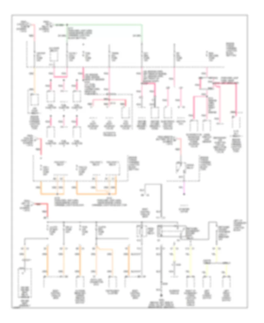
Power Distribution Wiring Diagram (3 of 5) for Chevrolet Impala 2000
List of elements for Power Distribution Wiring Diagram (3 of 5) for Chevrolet Impala 2000:
- (forward lamp harn, near left headlamp)
- 1-2 shift solenoid valve
- 2-3 shift solenoid valve
- A c435
- A.i.r. rly relay
- A/c cmpr relay
- A/c rly (coil) fuse 10a
- A12
- Air pmp rly fuse 30a
- Air pump relay
- Automatic transaxle
- B10
- Block (bottom))
- Body control module (bcm)
- C1 e11
- C11
- C113
- C12 c1
- C3 d1
- C311
- Clstr/ bcm fuse 10a
- Crank relay
- Data link connector (dlc)
- Dfi mdl fuse 15a
- Dr lk fuse 20a
- Driver heated seat relay module
- Driver seat assembly
- E1 c3
- Electronic ignition control module
- Eng devices fuse 10a
- Engine wiring harness junction block (bottom)
- Engine wiring harness junction block (top)
- Engine wirning harness junction block (top)
- Evaporative emissions canister purge solenoid valve
- F11
- F12
- Fan 1 cont fuse 25a
- Fan 2 & 3 cont fuse 25a
- Fan cont 1 relay
- Fan cont 2 relay
- Fan cont 3 relay
- From cooling fans fuse (diagram 1 of 5)
- From ign relay (diagram 1 of 5)
- From left i/p fuse (diagram 1 of 5)
- From remote battery stud e (diagram 1 of 5)
- From u/hood 2 fuse (diagram 1 of 5)
- Fuel inj fuse 15a
- Fuel injector
- G202 (behind left side of dash, on left side of brake pedal bracket)
- Head- lamp relay
- Heated oxygen sensor 1 (ho2s)
- Heated oxygen sensor 2 (ho2s)
- Ignition coil
- Impala
- Instrument cluster
- L36
- L36: (engine harn, left rear of engine) la1: (engine harn, left front of engine compt) s157
- La1
- Left front door window switch
- Left i/p accessory wiring junction block
- Left side window switch
- Lh htd st/bcm fuse 15a
- Mass airflow (maf) sensor
- Monte carlo
- Nc1,nc8
- Nca
- Nf2
- Outside rearview mirror remote control switch
- Oxy sen fuse 15a
- Pnk
- Pnk l36: (engine harn, engine near iat sensor) s109 la1: (fuel injector jumper harn, near fuel injector 1)
- Pnk s130
- Pwr mir fuse 2a
- Red
- Retained accessory power (rap) relay
- Retained accsry pwr brkr circuit breaker 30a
- Right i/p accessory wiring junction block (monte carlo)
- S115 red
- S131 (engine harn, right front of engine)
- S132 (forward lamp harn, inside engine wiring harness junction block (top)
- S179 (forward lamp harn, inside engine wiring harness junction block)
- S236
- Secondary air injection vacuum regulator solenoid valve
- Starter motor
- Sunroof module
- Tcc pwm solenoid valve
- Trans sol fuse 10a
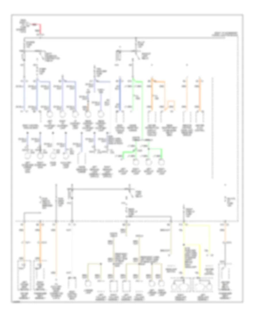
Power Distribution Wiring Diagram (4 of 5) for Chevrolet Impala 2000
List of elements for Power Distribution Wiring Diagram (4 of 5) for Chevrolet Impala 2000:
- (rear body harn, left front side of rear compt) s400
- A11
- A12 c3
- Auxiliary dome lamp
- B/u lp fuse 10a
- Backup lamp relay
- Batt rundown protection relay
- Body control module (bcm)
- C1 d4
- C3 e8
- C311
- C312
- C400
- D10
- Dic/rke fuse 10a
- Dome lamp
- Driver information display control module
- Driver seat assembly
- E3 c1
- E5 c3
- F1 c1
- F12
- F4 c1
- From right i/p 1 fuse (diagram 1 of 5)
- Front park lp fuse 15a
- H10
- H11
- H12
- Headlamp switch
- Heated seat relay module
- Heater & a/c control
- I/p compart- ment lamp
- Impala
- Inside rearview mirror
- Ip brp fuse 10a
- K10
- K11
- K12
- L10
- Left back-up lamp
- Left headlamp assembly
- Left i/p courtesy lamp
- Left license lamp
- Left power seat switch
- Left reading lamp assembly (impala)
- Left sunshade mirror lamp (dh6)
- Left taillamp assembly
- License lamp
- Monte carlo
- N10
- Nca
- Of rear compt) s400
- Park lamp relay
- Passenger seat assembly
- Pwr drop fuse 15a
- Pwr seats circuit breaker 30a
- Rear compart- ment courtesy lamp
- Rear compartment lid release relay (seo)
- Rear park lp fuse 15a
- Red
- Remote control door lock receiver (rcdlr)
- Rh htd st fuse 15a
- Right back-up lamp
- Right front side of roof)
- Right headlamp assembly
- Right i/p accessory wiring junction block
- Right i/p courtesy lamp
- Right license lamp
- Right power seat switch
- Right reading lamp assembly (impala)
- Right sunshade (dh6)
- Right taillamp assembly
- S176 (forward lamp harn, right side of engine compt, behind right headlamp)
- To auxiliary power drop connector (diagram 5 of 5)
- Trk/ roof brp fuse 15a
- W/ 9c1/ 9c6
- W/ c79
- W/ dd6
- W/ dh6
- W/ u68
- W/ ua6
- W/9c1/ 9c6
- W/o c79
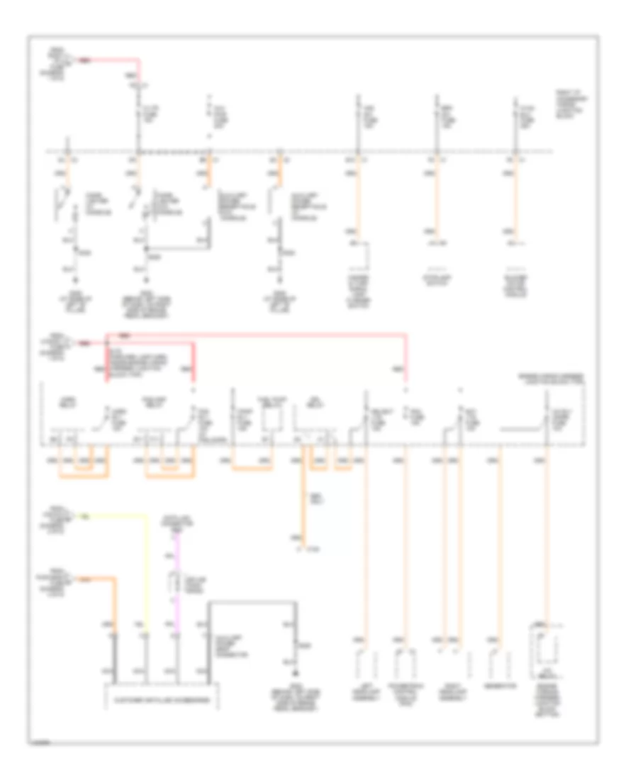
Power Distribution Wiring Diagram (5 of 5) for Chevrolet Impala 2000
List of elements for Power Distribution Wiring Diagram (5 of 5) for Chevrolet Impala 2000:
- A/c relay
- A/c rly (cmpr) fuse 10a
- Aux pwr fuse 20a
- Auxiliary power drop connector
- Auxiliary power receptacle (w/ console)
- Auxiliary power receptacle (w/o console)
- Block (top))
- Blower motor control module
- Brk sw fuse 15a
- C/ltr fuse 15a
- C122
- Cigar lighter (w/ console)
- Cigar lighter (w/o console)
- Customer installed accessories
- Data link connector (dlc)
- Drl relay
- Drl/ext lts fuse 15a
- E10
- E11
- Engine wiring harness junction block (top)
- Engine wirning harness junction block (bottom)
- Ext lts fuse 10a
- F/pmp rly fuse 15a
- F11
- Fog rly fuse 10a (w/ foglamps)
- Foglamp relay
- From cig/aux fuse (diagram 2 of 5)
- From pwr drop fuse (diagram 4 of 5)
- From right i/p 2 fuse (diagram 1 of 5)
- From u/hood 1 fuse (diagram 1 of 5)
- Fuel pump relay
- G202 (behind left side of dash, on right side of brake pedal bracket)
- G308 (at base of left "b" pillar)
- Generator
- Haz sw fuse 15a
- Hazard & turn signal lamp flasher switch
- Horn relay
- Horn rly fuse 15a
- Hvac blo fuse 25a
- Left headlamp assembly
- Nca
- Pcm fuse 15a
- Powertrain control module (pcm)
- Red
- Right headlamp assembly
- Right i/p accessory wiring junction block
- S178 (forward lamp harn, inside engine wiring harness junction red
- S229
- S320
- S338
- Seo only
- Splice pack sp205
- Stoplamp switch