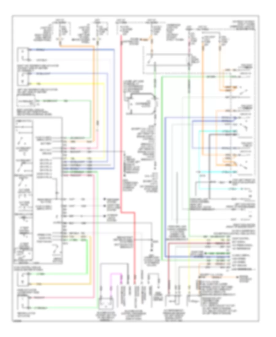
AIR CONDITIONING
Compressor Wiring Diagram for Chevrolet Impala 2005

List of elements for Compressor Wiring Diagram for Chevrolet Impala 2005:
- (3.4l (vin e): left front of engine compt, 4 cm from c112 breakout) (3.8l (vin k): left rear of engine, 6.5 cm from egr valve breakout) (except 3.8l (vin 1)) s158
- (on transaxle stud, near starter)
- +5v reference
- A/c cmpr relay
- A/c compressor clutch
- A/c compressor clutch diode (lower left side of engine, at a/c compressor)
- A/c press signal
- A/c refrigerant pressure sensor (on left side of engine compt, on liquid line)
- A/c rly (cmpr) fuse 10a
- A/c rly (coil) fuse 10a
- Comp control
- Computer data lines system
- E11
- F11
- G113 (3.8l (vin 1))
- G117 (except 3.8l (vin 1))
- Hot at all times
- Hot in run
- Low reference
- Nca
- Pnk
- Power distribution system
- Powertrain control module (pcm) (in air cleaner box)
- Serial data
- Underhood junction block (bottom) (on front of right strut tower)
- Underhood junction block (top) (on front of right strut tower)
Manual A/C Wiring Diagram for Chevrolet Impala 2005
List of elements for Manual A/C Wiring Diagram for Chevrolet Impala 2005:
- & manifold absolute pressure sensor breakout)
- (behind right center of dash, 8.5 cm from ignition switch breakout)
- (except 3.4l (vin e)) s186
- (forward lamp wiring harness, 31.5 cm from ambient air temperature sensor breakout)
- (forward lamp wiring harness, near left headlamp, 18.5 cm from g101 breakout)
- (in air cleaner box) powertrain control module (pcm)
- (lower left side of engine, at a/c compressor) a/c compressor clutch diode
- (on front of right strut tower) underhood junction block (bottom)
- (top left front of radiator support) g101
- +5v reference
- A/c cmpr relay
- A/c compressor clutch
- A/c cruise fuse 10a
- A/c press signal
- A/c refrigerant pressure sensor (on left side of engine compt, on liquid line)
- A/c request ind
- A/c request sig
- A/c request switch
- A/c rly (cmpr) fuse 10a
- A/c rly (coil) fuse 10a
- A10
- A11
- A12
- B blower motor speed ctrl
- B10
- B11
- B12
- Battery
- Blower motor (on right bottom of heater-a/c assembly)
- Blower motor control processor (lower right side of dash)
- Body control module (behind left side of dash, above parking brake lever)
- C battery positive voltage
- C10
- Class 2 serial
- Comp control
- Computer data lines system
- D temp control switch
- D4 c1
- Defog switch
- Defogger system
- Dic/ rke fuse 10a
- Door ctrl
- Door ctrl a
- Door ctrl b
- Dr ctrl a
- Dr ctrl b
- E11
- Ect ground
- Ect signal
- Engine controls system
- Engine coolant temperature (ect) sensor (3.4l: near coolant outlet, on left rear of engine) (3.8l: below coolant outlet, on left rear of engine)
- F11
- Fan cont 1 fuse 25a
- Fan cont 1 relay
- Fan cont 2 & 3 fuse 25a
- Fan cont 2 relay
- Fan cont 3 relay
- G113 (3.8l (vin 1)) g117 (except 3.8l (vin 1)) (on transaxle stud, near starter)
- G201 (under dash to right side of steering column)
- G202 (under dash, in center)
- G203 (under dash, to right of steering column)
- Ground
- High
- High speed
- Hot at all times
- Hot in on
- Hvac blower fuse 30a
- Hvac class 2 serial data
- Hvac control module (middle center of dash)
- I/p junction block (left) (left side of dash, behind access panel)
- I/p junction block (right) (right side of dash, behind access panel)
- Ign 3 volt
- Illum
- Interior lights system
- Left air temperature actuator (on left side of heater- a/c assembly)
- Left cooling fan (front of engine compt)
- Logic
- Low
- Low reference
- Low speed
- Mode actuator (lower right side of dash)
- Mode switch
- Nca
- Off blower motor switch
- Out side air ind
- Out side air switch
- P temp control switch
- Pnk
- Position sig
- Power distribution system
- Rear defog rly ctrl
- Recirculation actuator
- Recirculation ind
- Recirculation switch
- Red
- Right air temperature actuator (on right side of heater- a/c assembly)
- Right cooling fan (front of engine compt)
- S148
- S158 (except 3.8l (vin 1)) (3.4l (vin e): left front of engine compt, 4 cm from c112 breakout) (3.8l (vin k): left rear of engine, 6.5 cm from egr valve breakout)
- S175
- S229
- Speed ctrl
- Tan
- Underhood junction block (top) (on front of right strut tower)