AIR CONDITIONING
Air Conditioning Wiring Diagrams, C60 (1 of 2) for Chevrolet Lumina LTZ 1997

List of elements for Air Conditioning Wiring Diagrams, C60 (1 of 2) for Chevrolet Lumina LTZ 1997:
- (i/p harn, 4cm from i/p compt lamp breakout)
- (i/p harn, behind right side of driver knee bolster)
- A/c solenoid
- B-lv
- Bi-level solenoid
- Blend
- Blower motor
- Blower motor relay (behind right side of i/p)
- Blower motor resistors (behind right side of a/c module)
- Blower switch
- C 1995 vftc
- Def
- Defrost solenoid
- Exterior lights input
- Fuse 15a
- Fuse 20a
- Fuse block
- G202 (behind i/p left side of brake pedal bracket)
- G202 (behind i/p right side of brake pedal bracket)
- Heater and a/c control
- Heater solenoid
- Hot at al times
- Hot in run
- Htr
- Interior lights input
- Max
- Norm
- Off
- Recirc solenoid
- Red
- S213
- S233
- Solid state
- Tan
- Temperature control
- Vacuum/electric solenoid (behind i/p, right of plenum)
- Vnt
- Vnt b-lv
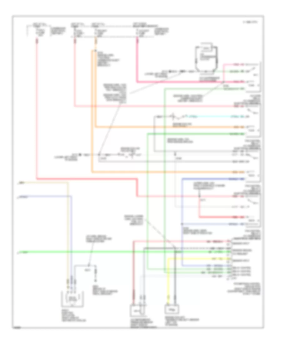
Air Conditioning Wiring Diagrams, C60 (2 of 2) for Chevrolet Lumina LTZ 1997
List of elements for Air Conditioning Wiring Diagrams, C60 (2 of 2) for Chevrolet Lumina LTZ 1997:
- (engine harn, 10cm from underhood elect center 1 breakout)
- (engine harn, 13cm from eng cooling fan 1 breakout) (vin m) (engine harn, 13cm from auto trans conn breakout) (vin x)
- (engine harn, 7cm from engine ground)
- (engine jumper harn, 2cm from fuel inj 3 breakout)
- (i/p harn, behind right side of driver knee bolster)
- (wiper harn, 4cm from windshield washer pump breakout)
- +5v
- A/c cmpr relay (in underhood electrical center 1)
- A/c compressor clutch
- A/c compressor clutch diode
- A/c cont fuse 10a
- A/c refrigerant pressure sensor (right side of engine compartment)
- A/c request
- B10
- C 1995 vftc
- C10
- Engine coolant temperature (ect) sensor (left top of engine)
- Engine cooling fan motor 1
- Engine cooling fan motor 2
- Fan 3 fuse 25a
- Fan control relay 1 (in underhood electrical center 1)
- Fan control relay 2 (in underhood electrical center 1)
- Fan control relay 3 (in underhood electrical center 2)
- G110 (lower left front of engine)
- G202 (behind i/p right side of brake pedal bracket)
- Hot at all times
- Hot in run, bulb test or start
- Maxi fuse 1 30a
- Nca
- Pcm bat fuse 20a
- Pnk
- Powertrain control module (pcm) (right side of engine compartment, forward of strut tower)
- Red
- Relay control
- Right electric actuator (right side of heater-a/c module)
- S102 (engine harn, 17cm from underhood elect center 1 breakout)
- S105
- S121
- S158
- S163 (engine harn, near right side of radiator)
- S165
- S171
- S213
- Sensor ground
- Sensor input
- Solid state
- Underhood electrical center 1
- Underhood electrical center 2
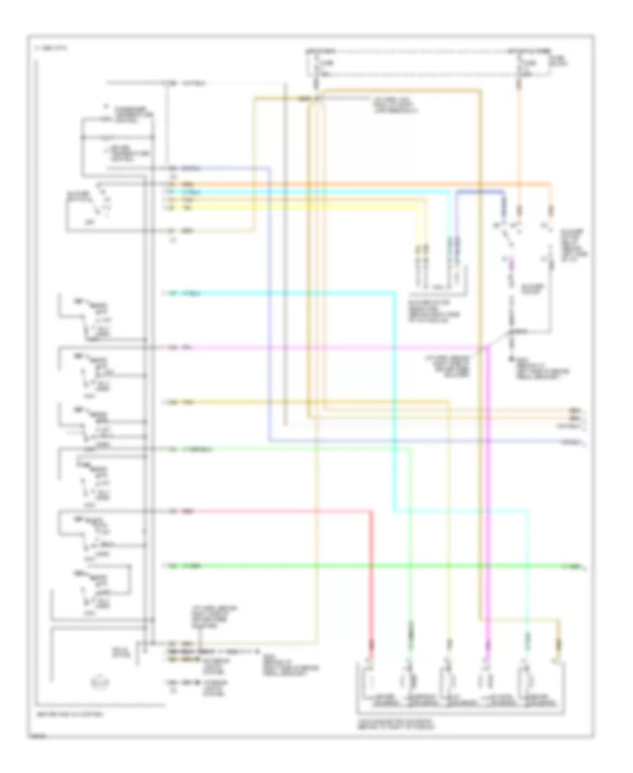
Air Conditioning Wiring Diagrams, CJ3 (1 of 2) for Chevrolet Lumina LTZ 1997
List of elements for Air Conditioning Wiring Diagrams, CJ3 (1 of 2) for Chevrolet Lumina LTZ 1997:
- (i/p harn, 4cm from i/p compt lamp breakout)
- (i/p harn, behind right side of driver knee bolster)
- A/c solenoid
- B-lv
- Bi-level solenoid
- Blend
- Blower motor
- Blower motor relay (behind left side of i/p)
- Blower motor resistors (behind right side of a/c module)
- Blower switch
- C 1995 vftc
- Def
- Defrost solenoid
- Driver temperature control
- Exterior lights system
- Fuse 15a
- Fuse 20a
- Fuse block
- G202 (behind i/p left side of brake pedal bracket)
- G202 (behind i/p right side of brake pedal bracket)
- Heater and a/c control
- Heater solenoid
- Hot at al times
- Hot in run
- Htr
- Interior lights system
- Max
- Norm
- Off
- Passenger temperature control
- Recirc solenoid
- Red
- S213
- S233
- Solid state
- Tan
- Vacuum/electric solenoid (behind i/p, right of plenum)
- Vnt
- Vnt b-lv
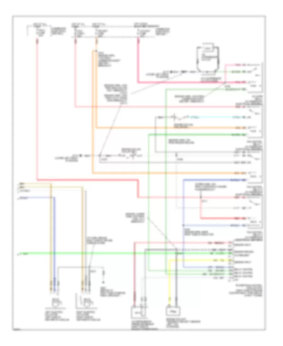
Air Conditioning Wiring Diagrams, CJ3 (2 of 2) for Chevrolet Lumina LTZ 1997
List of elements for Air Conditioning Wiring Diagrams, CJ3 (2 of 2) for Chevrolet Lumina LTZ 1997:
- (engine harn, 10cm from underhood elect center 1 breakout)
- (engine harn, 13cm from eng cooling fan 1 breakout) (vin m) (engine harn, 13cm from auto trans conn breakout) (vin x)
- (engine harn, 7cm from engine ground)
- (engine jumper harn, 2cm from fuel inj 3 breakout)
- (i/p harn, behind right side of driver knee bolster)
- (wiper harn, 4cm from windshield washer pump breakout)
- +5v
- A/c cmpr relay (in underhood electrical center 1)
- A/c compressor clutch
- A/c compressor clutch diode
- A/c cont fuse 10a
- A/c refrigerant pressure sensor (right side of engine compartment)
- A/c request
- B10
- C10
- Engine coolant temperature (ect) sensor (left top of engine)
- Engine cooling fan motor 1
- Engine cooling fan motor 2
- Fan 3 fuse 25a
- Fan control relay 1 (in underhood electrical center 1)
- Fan control relay 2 (in underhood electrical center 1)
- Fan control relay 3 (in underhood electrical center 2)
- G110 (lower left front of engine)
- G202 (behind i/p right side of brake pedal bracket)
- Hot at all times
- Hot in run, bulb test or start
- Left electric actuator (left side of heater-a/c module)
- Maxi fuse 1 30a
- Nca
- Pcm bat fuse 20a
- Pnk
- Powertrain control module (pcm) (right side of engine compartment, forward of strut tower)
- Red
- Relay control
- Right electric actuator (right side of heater-a/c module)
- S102 (engine harn, 17cm from underhood elect center 1 breakout)
- S105
- S121
- S158
- S163 (engine harn, near right side of radiator)
- S165
- S171
- S213
- Sensor ground
- Sensor input
- Solid state
- Underhood electrical center 1
- Underhood electrical center 2