AIR CONDITIONING
Compressor Wiring Diagram for Chevrolet Malibu Classic LT 2008

List of elements for Compressor Wiring Diagram for Chevrolet Malibu Classic LT 2008:
- 2.2l
- 3.5l
- 5v ref
- A/c clu fuse 1 10a
- A/c clutch relay
- A/c compressor clutch (lower right front of engine)
- A/c refrigerant pressure sensor (left of right front strut tower)
- A/c req sig
- A/c request ind
- A/c request switch
- Body control module (bcm) (under front of center console)
- Clu rly ctrl
- Computer data lines system
- Data bus+
- Data bus-
- E1 x2
- E8 x1
- Engine control module (ecm) (left side of engine compt, forward of battery)
- G106 (2.2l: on engine, below generator) (3.5l: on transmission, near park/neutral position switch)
- High speed gm lan serial data +
- High speed gm lan serial data -
- Hot at all times
- Hot in run or start
- Hvac control module (3 & 4) (center of dash)
- Logic
- Low ref
- Low speed gm lan serial data
- Sens sig
- Tan
- Underhood fuse block (on left side of engine compt)
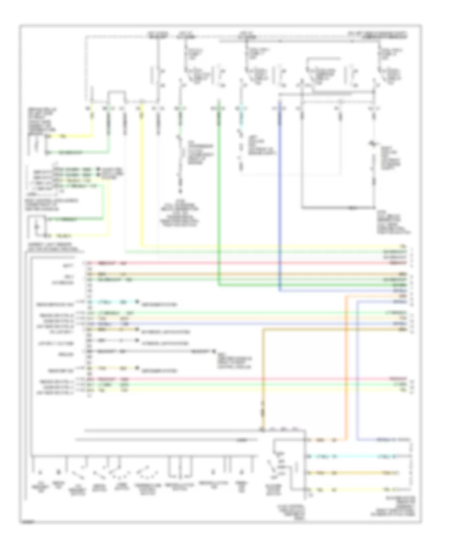
Manual A/C Wiring Diagram (1 of 2) for Chevrolet Malibu Classic LT 2008
List of elements for Manual A/C Wiring Diagram (1 of 2) for Chevrolet Malibu Classic LT 2008:
- (behind grille, on left side of front impact bar) ambient air temperature sensor
- (on left side of engine compt) underhood fuse block
- 87a
- A/c clu fuse 1 10a
- A/c clutch relay
- A/c compressor clutch (lower right front of engine)
- A/c req sig
- A/c request ind
- A/c request switch
- A10
- A11
- A11 x2
- A12
- A2 x1
- Air temp dr ctrl a
- Air temp dr ctrl b
- Ambient light sensor (on top of dash trim pad)
- B10
- B10 x2
- B11
- B12
- B9 x3
- Batt
- Blower motor resistor assembly (right side of dash, on rear of hvac case)
- Blower motor switch
- Body control module (bcm) (under front of center console)
- Computer data lines system
- Cool fan 1 fuse 17 30a
- Cool fan 2 fuse 18 30a
- Cool/ fan 1 relay
- Cool/ fan 2 relay
- Cool/fan ser/par relay
- Defog ind
- Defog switch
- Defogger system
- E1 x2
- E8 x1
- Exterior lights system
- Fresh air ind
- G106 (2.2l: below generator) (3.5l: near park/neutral position switch)
- G106 (2.2l: on engine, below generator) (3.5l: on transmission, near park/neutral position switch)
- G201 (center console, front of body control module)
- Ground
- High
- Hot at all times
- Hot in run or start
- Hvac control module (3 & 4) (center of dash)
- Ign 3
- Interior lights system
- Left cooling fan (on front of engine compt)
- Lmp sply voltage
- Logic
- Low
- Lt sen low
- Lt sen sig
- Mode dr ctrl a
- Mode dr ctrl b
- Mode switch
- Off
- Pk lmp sply
- Rear def ind
- Rear defog sw sig
- Recirc dr ctrl a
- Recirc dr ctrl b
- Recirculation ind
- Recirculation switch
- Right cooling fan (on front of engine compt)
- Ser data
- Tan
- Temperature control switch
- X1 e3
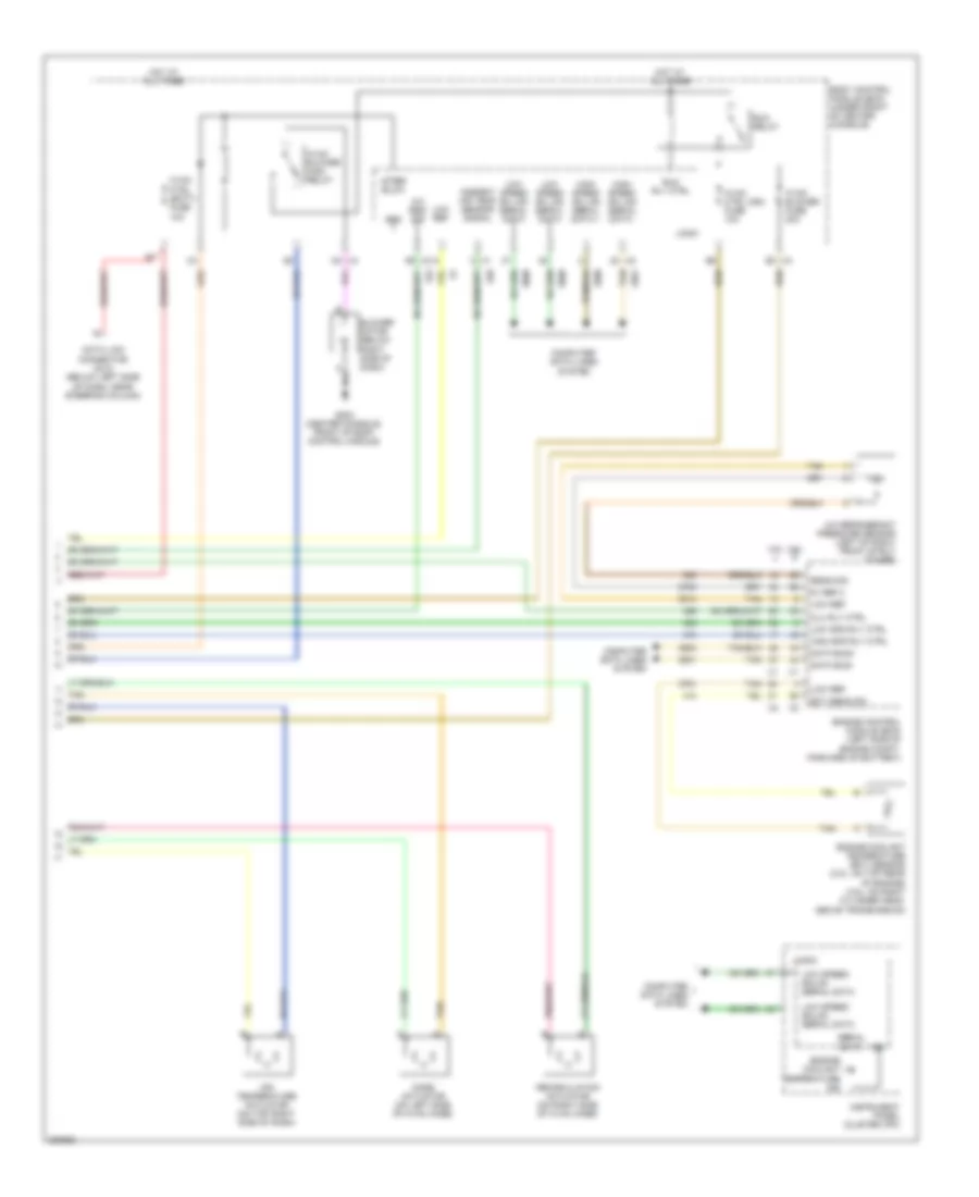
Manual A/C Wiring Diagram (2 of 2) for Chevrolet Malibu Classic LT 2008
List of elements for Manual A/C Wiring Diagram (2 of 2) for Chevrolet Malibu Classic LT 2008:
- 2.2l
- 3.5l
- 5v ref 2
- A/c refrigerant pressure sensor (left of right front strut tower)
- A/c req sig
- After blow
- Air temperature actuator (on top right side of dash)
- Ambient air temp sensor signal
- Blower motor (below right side of dash)
- Body control module (bcm) (under front of center console)
- Clu rly ctrl
- Computer data lines system
- D4 x4
- Data bus+
- Data bus-
- Data link connector (dlc) (below left side of dash, near steering column)
- Ect sens sig
- Engine control module (ecm) (left side of engine compt, forward of battery)
- Engine coolant temperature (ect) sensor (2.2l: on top rear of engine) (3.5l: on right cylinder head, above transmission)
- Engine coolant temperature ind
- G203 (center console, front of body control module)
- Gnd
- High spd rly ctrl
- High speed gm lan serial data +
- High speed gm lan serial data -
- Hot at all times
- Hvac blower fuse 20a
- Hvac blower high relay
- Hvac ctrl (batt) fuse 10a
- Hvac ctrl (ign) fuse 10a
- Ign
- Instrument panel cluster (ipc)
- Logic
- Low ref
- Low spd rly ctrl
- Low speed gm lan serial data
- Low speed gmlan serial data
- Mode actuator (on left side of hvac case)
- Recirculation actuator (on right side of hvac case)
- Run relay
- Run rly ctrl
- Sens sig
- Serial data
- Tan
- X4 b3