AIR CONDITIONING
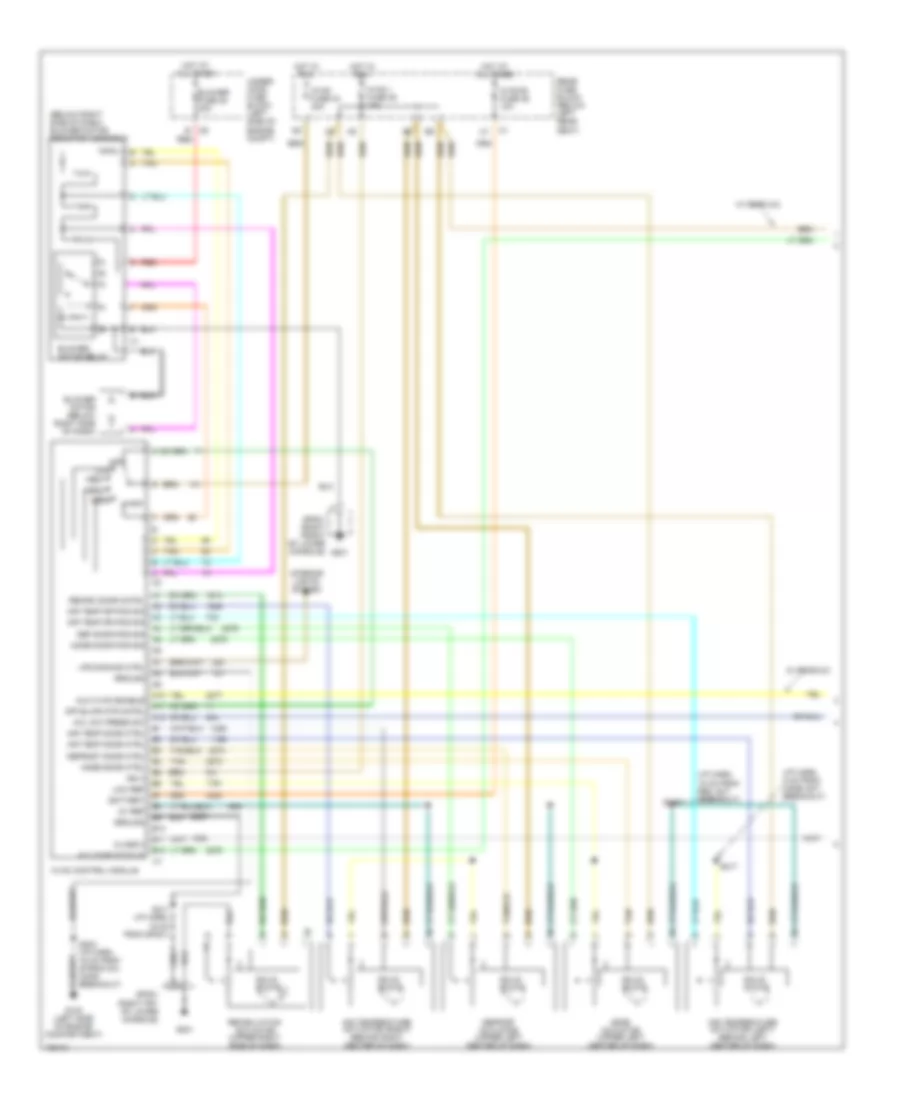
Automatic A/C Wiring Diagram, Long Wheel Base (1 of 3) for Chevrolet TrailBlazer 2004

List of elements for Automatic A/C Wiring Diagram, Long Wheel Base (1 of 3) for Chevrolet TrailBlazer 2004:
- (i/p harn, 15 cm from rec act breakout)
- (i/p harn, 5 cm from mode act breakout)
- 5v ref
- A/c comp status
- A/c low press sw
- A10
- A11
- A12
- Air temp door ctrl
- Air temp dr pos sig
- Air temperature actuator (left) (behind left center of dash)
- Air temperature actuator (right) (behind right center of dash)
- Ambient air temp sig
- Ambient air temperature sensor (on left center of radiator support)
- Ambient light
- Ambient light/ sunload sensor assembly (top center of dash)
- B10
- B11
- B12
- Battery
- Blower fuse 35 40a
- Blower motor
- Blower motor control module
- Blwr mtr spd ctrl
- Class 2
- Coolant bypass ctrl
- Coolant bypass valve
- Def door pos sig
- Defrost actuator (upper left center of dash)
- Defrost door ctrl
- G102 (left side of engine compartment)
- G103 (left front of engine compt)
- G201
- G302 (on lower left "b" pillar)
- Ground
- Hot at all times
- Hot in run
- Hvac control module
- Hvac i fuse 39 10a
- Hvac-b fuse 36 10a
- Ign 3
- Inside air temp ctrl
- Inside air temp sig
- Inside air temperature sensor (top of left "b" pillar, behind trim)
- Interior lights system
- Left sensor
- Low ref
- Low reference
- Lower left air temperature sensor (behind lower left of dash, on air duct)
- Lower right air temperature sensor (behind lower right of dash, on air duct)
- Lps dimming ctrl
- Lwr lt air temp sig
- Lwr rt air temp sig
- Mode actuator (upper left center of dash)
- Mode door ctrl
- Mode door pos sig
- Rear fuse block (below left rear seat)
- Recirc door cntrl
- Recirc dr pos sig
- Recirulation actuator (upper right side of dash)
- Red
- Right sensor
- S202 (i/p harn, 16.5 cm from strng col conn breakout)
- S211 (i/p harn, 16 cm from sp201)
- S216
- S217
- S271 (i/p harn, 14.5 cm from dash comp lamp breakout)
- S302 (5 cm from main harn breakout)
- Solid state
- Sp201 (right front of lower console)
- Sp201 (right frt of lower console)
- Tan
- Under- hood fuse block (left side of engine compt)
- Upper left air temperature sensor (behind upper left center of dash)
- Upper right air temperature sensor (behind upper right center of dash)
- Uppr lt air temp sig
- Uppr rt air temp sig
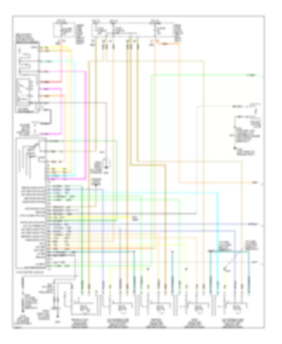
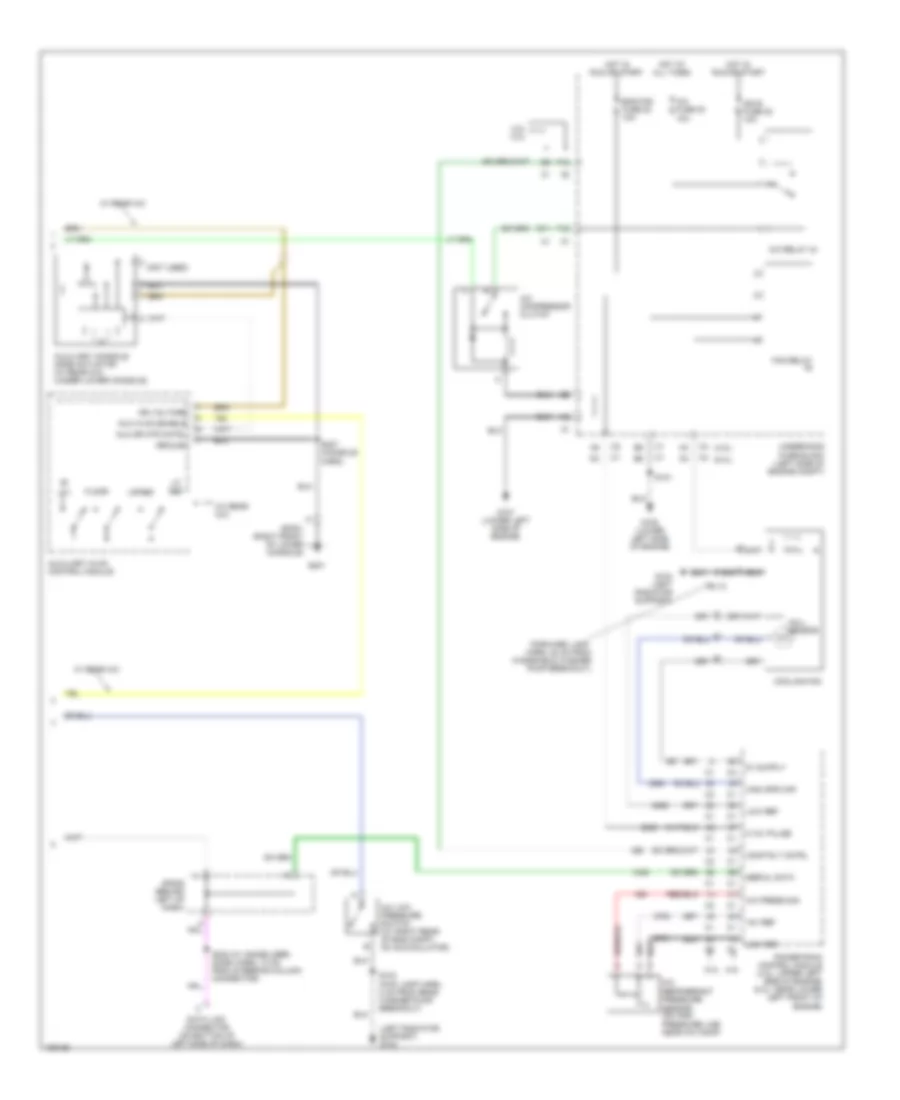
Automatic A/C Wiring Diagram, Long Wheel Base (2 of 3) for Chevrolet TrailBlazer 2004
List of elements for Automatic A/C Wiring Diagram, Long Wheel Base (2 of 3) for Chevrolet TrailBlazer 2004:
- (4.2l)
- (5.3l)
- (forward lamp harn, 20 cm from windshield washer pump breakout)
- (left radiator support) g103
- +5v ref
- 0-12v pulse
- 4.2l 5.3l
- 5.3l 4.2l
- A/c compressor clutch
- A/c fuse 30 10a
- A/c low pressure switch (at right rear of eng compt, on accumulator)
- A/c press sig
- A/c refrigerant pressure sensor (on high pressure line near a/c comp)
- A/c relay 44
- A12
- Ambient light sens
- B11
- B12
- Body control module (beneath left rear seat, on rear fuse block)
- Comp rly cntrl
- Cooling fan
- Cooling fan relay
- D11
- Data link connector (on bottom of left side of dash)
- Eng fan fuse 20 10a
- F10
- F12
- G103 (left radiator support)
- G107 (lower left side of engine)
- G108 (lower left side of engine)
- Hall sensor
- High spd maf
- Hot at all times
- Hot in run or start
- Ign e fuse 22 10a
- Low ref
- Low reference
- Lt sunload sens sig
- Powertrain control module (4.2l: upper left side of engine) (5.3l: near lower left front of engine)
- Rt sunload sens sig
- S101
- S103 (fwd lamp harn, 8 cm from rear washer pump breakout)
- S113
- S232 (w/ immobilizer) (dash harn, 10 cm from steering column connector)
- Serial data
- Sp205 (behind left of dash)
- Underhood fuse block (left side of engine compt)
Automatic A/C Wiring Diagram, Long Wheel Base (3 of 3) for Chevrolet TrailBlazer 2004
List of elements for Automatic A/C Wiring Diagram, Long Wheel Base (3 of 3) for Chevrolet TrailBlazer 2004:
- (lower console harness, between aux hvac module & c309)
- (lower console harness,near aux hvac module)
- (not used)
- (on lower right "d" pillar) g402
- 30a
- 5v reference
- A10
- A11
- A12
- A13
- A14
- A15
- A16
- Auc hvac enable
- Aux act door ctlr
- Aux air temp dr ctlr
- Aux air temp dr pos
- Aux blwr mtr
- Aux mode door ctrl
- Aux mode dr pos sig
- Auxiliary air temperature actuator
- Auxiliary blower motor (on right side of cargo area, behind trim panel)
- Auxiliary blower motor control processor (in rear hvac module, behind right rear interior panel)
- Auxiliary blower motor fuse
- Auxiliary console mode actuator
- Auxiliary mode actuator (below center of dash)
- B10
- B11
- B12
- B13
- B14
- B15
- B16
- Battery
- Class 2 data
- Console mode dr ctrl
- Ctrl mode dr pos sig
- Front auxiliary blower motor switch
- G201
- Ground auxiliary hvac control module
- Hot at all times
- Interior lights system
- Low reference
- Off
- Rear
- Rear fuse block (below left rear seat)
- Red
- Rr hvac fuse 13 30a
- S307 (console harness)
- S324
- S325
- S326
- S402
- Sp201 (right front of lower console)
Automatic A/C Wiring Diagram, Short Wheel Base (1 of 2) for Chevrolet TrailBlazer 2004
List of elements for Automatic A/C Wiring Diagram, Short Wheel Base (1 of 2) for Chevrolet TrailBlazer 2004:
- (i/p harn, 15 cm from mode act breakout)
- (i/p harn, 15 cm from rec act breakout)
- 5v ref
- A/c comp status
- A/c low press sw
- A10
- A11
- A12
- Air temp door ctrl
- Air temp dr pos sig
- Air temperature actuator (left) (behind left center of dash)
- Air temperature actuator (right) (behind right center of dash)
- Ambient air temp sig
- Ambient air temperature sensor (on left center of radiator support)
- Ambient light
- Ambient light/ sunload sensor assembly (top center of dash)
- B10
- B11
- B12
- Battery
- Blower fuse 35 40a
- Blower motor
- Blower motor control module
- Blwr mtr spd ctrl
- Class 2
- Def door pos sig
- Defrost actuator (upper left center of dash)
- Defrost door ctrl
- G102 (left side of engine compartment)
- G201
- G302 (on lower left "b" pillar)
- Ground
- Hot at all times
- Hot in run
- Hvac control module
- Hvac i fuse 39 10a
- Hvac-b fuse 36 10a
- Ign 3
- Inside air temp ctrl
- Inside air temp sig
- Inside air temperature sensor (top of left "b" pillar, behind trim)
- Interior lights system
- Left sensor
- Low ref
- Low reference
- Lower left air temperature sensor (behind lower left of dash, on air duct)
- Lower right air temperature sensor (behind lower right of dash, on air duct)
- Lps dimming ctrl
- Lwr lt air temp sig
- Lwr rt air temp sig
- Mode actuator (upper left center of dash)
- Mode door ctrl
- Mode door pos sig
- Rear fuse block (below left rear seat)
- Recirc door cntrl
- Recirc dr pos sig
- Recirulation actuator (upper right side of dash)
- Red
- Right sensor
- S202 (i/p harn, 16.5 cm from strng col conn breakout)
- S211 (i/p harn, 16 cm from sp201)
- S216
- S217
- S271 (i/p harn, 14.5 cm from dash comp lamp breakout)
- S302 (5 cm from main harn breakout)
- Solid state
- Sp201 (right front of lower console)
- Sp201 (right frt of lower console)
- Tan
- Under- hood fuse block (left side of engine compt)
- Upper left air temperature sensor (behind upper left center of dash)
- Upper right air temperature sensor (behind upper right center of dash)
- Uppr lt air temp sig
- Uppr rt air temp sig
- W/ rear a/c
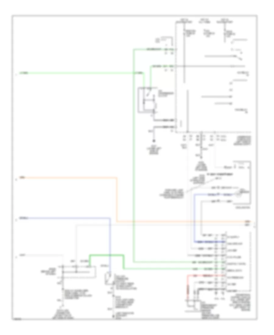
Automatic A/C Wiring Diagram, Short Wheel Base (2 of 2) for Chevrolet TrailBlazer 2004
List of elements for Automatic A/C Wiring Diagram, Short Wheel Base (2 of 2) for Chevrolet TrailBlazer 2004:
- (4.2l)
- (5.3l)
- (forward lamp harn, 20 cm from windshield washer pump breakout)
- (left radiator support) g103
- (not used)
- (w/ rear a/c)
- +5v ref
- 0-12v pulse
- 4.2l
- 4.2l 5.3l
- 5.3l
- A/c compressor clutch
- A/c fuse 30 10a
- A/c low pressure switch (at right rear of eng compt, on accumulator)
- A/c press sig
- A/c refrigerant pressure sensor (on high pressure line near a/c comp)
- A/c relay 44
- A12
- Ambient light sens
- Aux blwr hi spd
- Aux blwr lo spd
- Aux mode dr
- Auxiliary blower motor (w/ rear a/c) (below center of dash)
- Auxiliary console mode actuator (w/ rear a/c) (below center of dash)
- Auxiliary hvac control module
- B11
- B12
- Batt
- Body control module (beneath left rear seat, on rear fuse block)
- Class 2 data
- Comp rly cntrl
- Cooling fan
- D11
- Data link connector (on bottom of left side of dash)
- Eng fan fuse 20 10a
- F10
- F12
- Fan relay
- G103 (under left radiator support)
- G107 (lower left side of engine)
- G108 (lower left side of engine)
- G201
- Ground
- Hall sensor
- High spd maf
- Hot at all times
- Hot in run or start
- Ign e fuse 22 10a
- Low ref
- Low reference
- Lt sunload sens sig
- Mode
- Off
- Powertrain control module (4.2l: upper left side of engine) (5.3l: near lower left front of engine)
- Rt sunload sens sig
- S101
- S103 (fwd lamp harn, 8 cm from rear washer pump breakout)
- S113
- S232 (w/ immobilizer) (i/p harn, 10 cm from steering column connector)
- S307 (console harn)
- Serial data
- Sp201 (right front of lower console)
- Sp205 (behind left of dash)
- Underhood fuse block (left side of engine compt)
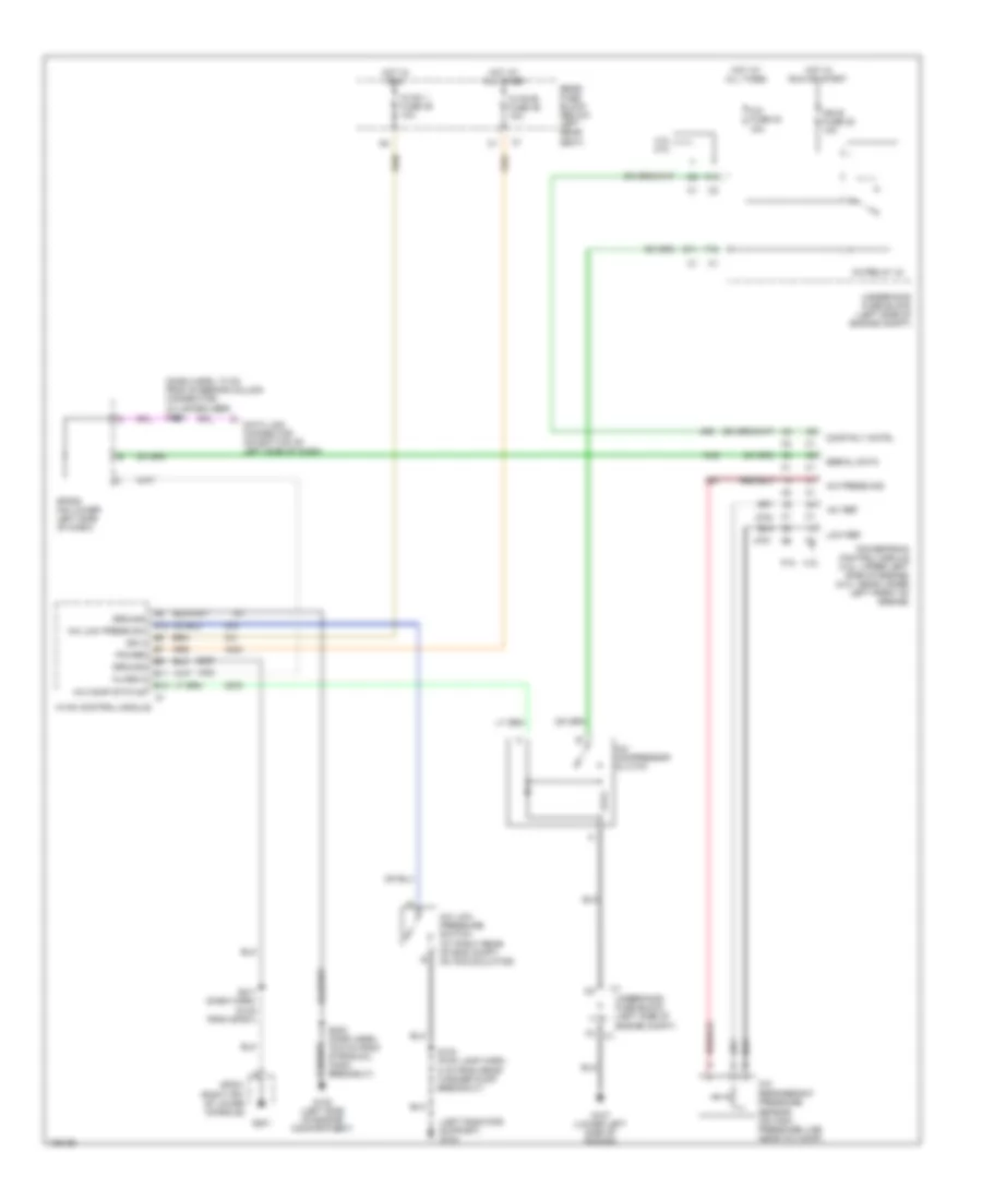
Compressor Wiring Diagram for Chevrolet TrailBlazer 2004
List of elements for Compressor Wiring Diagram for Chevrolet TrailBlazer 2004:
- (dash harn, 10 cm from steering column connector) (w/ immobilizer) s232
- (left radiator support) g103
- +5v ref
- 4.2l 5.3l
- 5.3l 4.2l
- A/c compressor clutch
- A/c comp status
- A/c fuse 30 10a
- A/c low press sw
- A/c low pressure switch (at right rear of eng compt, on accumulator)
- A/c press sig
- A/c refrigerant pressure sensor (on high pressure line near a/c comp)
- A/c relay 44
- A12
- B11
- B12
- Class 2
- Comp rly cntrl
- D11
- Data link connector (on bottom of left side of dash)
- F10
- F12
- G102 (left side of engine compartment)
- G107 (lower left side of engine)
- G201
- Ground
- Hot at all times
- Hot in run
- Hot in run or start
- Hvac 1 fuse 39 10a
- Hvac control module
- Hvac-b fuse 36 10a
- Ign 3
- Ign e fuse 22 10a
- Low ref
- Power
- Powertrain control module (4.2l: upper left side of engine) (5.3l: near lower left front of engine)
- Rear fuse block (below left rear seat)
- S103 (fwd lamp harn, 8 cm from rear washer pump breakout)
- S202 (dash harn, 16.5 cm from strng col conn breakout)
- S211 (dash harn, 16 cm from sp201)
- Serial data
- Sp201 (right frt of lower console)
- Sp205 (on lower left side of dash)
- Underhood fuse block (left side of engine compt)
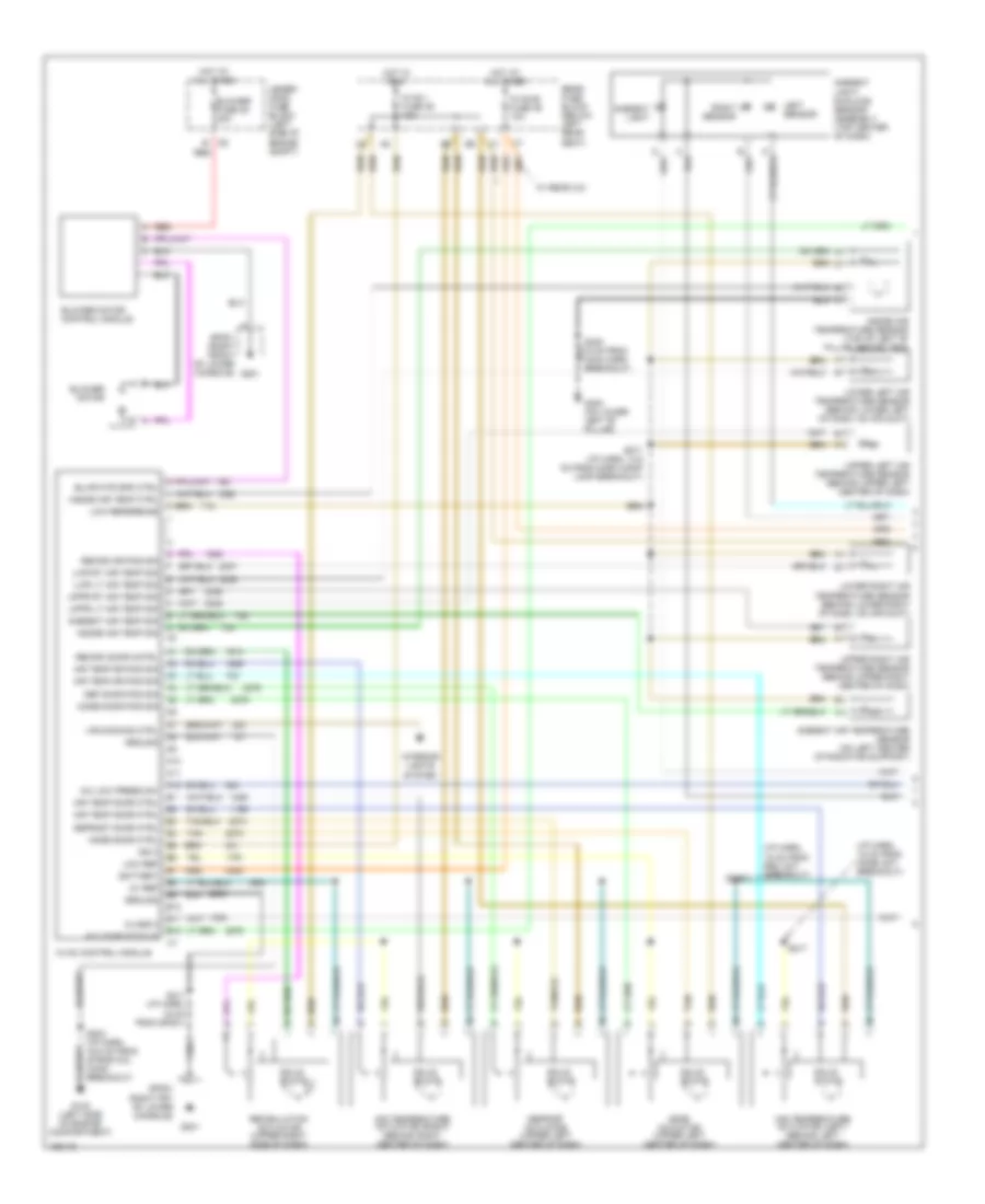
Manual A/C Wiring Diagram, Long Wheel Base (1 of 3) for Chevrolet TrailBlazer 2004
List of elements for Manual A/C Wiring Diagram, Long Wheel Base (1 of 3) for Chevrolet TrailBlazer 2004:
- (below right side of dash) blower motor resistor assembly
- (i/p harn, 15 cm from rec act breakout)
- (i/p harn, 5 cm from mode act breakout)
- (not used
- 5v ref
- A/c comp status
- A/c low press sw
- A10
- A11
- A12
- Air temp door ctrl
- Air temp dr pos sig
- Air temperature actuator (left) (behind left center of dash)
- Air temperature actuator (right) (behind right center of dash)
- B10
- B11
- B12
- Battery
- Blower fuse 35 40a
- Blower motor (below right side of dash)
- Blower motor relay
- Class 2
- Coolant bypass valve
- Def door pos sig
- Defrost actuator (upper left center of dash)
- Defrost door ctrl
- G102 (left side of engine compartment)
- G103 (left front of engine compt)
- G201
- Ground
- High
- Hot at all times
- Hot in run
- Htr water ctrl sol
- Hvac control module
- Hvac fuse 44 30a
- Hvac i fuse 39 10a
- Hvac-b 10a
- Ign 3
- Interior lights system
- Low
- Low ref
- Lps dimming ctrl
- Med1
- Med2
- Med3
- Mode actuator (upper left center of dash)
- Mode door ctrl
- Mode door pos sig
- Off
- Off blwr mtr cntrl
- Rear fuse block (below left rear seat)
- Recirc door cntrl
- Recirulation actuator (upper right side of dash)
- Red
- S202 (i/p harn, 16 cm from strng col conn breakout)
- S211 (i/p harn, 16 cm from sp201)
- S216
- S217
- Solid state
- Sp201 (right front of lower console)
- Sp201 (right frt of lower console)
- Tan
- Under- hood fuse block (left side of engine compt)
Manual A/C Wiring Diagram, Long Wheel Base (2 of 3) for Chevrolet TrailBlazer 2004
List of elements for Manual A/C Wiring Diagram, Long Wheel Base (2 of 3) for Chevrolet TrailBlazer 2004:
- (4.2l)
- (5.3l)
- (forward lamp harn, 20 cm from windshield washer pump breakout)
- (left radiator support) g103
- +5v ref
- 0-12v pulse
- 4.2l 5.3l
- 5.3l 4.2l
- A/c compressor clutch
- A/c fuse 30 10a
- A/c low pressure switch (at right rear of eng compt, on accumulator)
- A/c press sig
- A/c refrigerant pressure sensor (on high pressure line near a/c comp)
- A/c relay
- Comp rly cntrl
- Cooling fan
- D11
- Data link connector (on bottom of left side of dash)
- E12
- Eng fan fuse 20 10a
- F12
- Fan relay
- G103 (left side of radiator support)
- G107 (lower left side of engine)
- G108 (lower left side of engine)
- Hall sensor
- High spd maf
- Hot at all times
- Hot in run or start
- Ign e fuse 22 10a
- Low ref
- Powertrain control module (4.2l: upper left side of engine) (5.3l: near lower left front of engine)
- S101
- S103 (fwd lamp harn, 8 cm from rear washer pump breakout)
- S113
- S232 (w/ immobilizer) (dash harn, 10 cm from steering column connector)
- Serial data
- Sp205 (behind left of dash)
- Underhood fuse block (left side of engine compt)
Manual A/C Wiring Diagram, Long Wheel Base (3 of 3) for Chevrolet TrailBlazer 2004
List of elements for Manual A/C Wiring Diagram, Long Wheel Base (3 of 3) for Chevrolet TrailBlazer 2004:
- (lower console harness, between aux hvac module) & c309)
- (not used)
- (on lower right "d" pillar) g402
- 30a
- 5v reference
- A10
- A11
- A12
- Auc hvac enable
- Aux act door ctlr
- Aux air temp dr ctlr
- Aux air temp dr pos
- Aux blwr mtr auxiliary hvac control module
- Aux mode door ctrl
- Aux mode dr pos sig
- Auxiliary air temperature actuator
- Auxiliary blower motor (on right side of cargo area, behind trim panel)
- Auxiliary blower motor control processor (in rear hvac module, behind right rear interior panel)
- Auxiliary blower motor fuse
- Auxiliary mode actuator (below center of dash)
- B10
- B11
- B12
- Battery
- Class 2 data
- Console mode actuator
- Console mode dr ctrl
- Ctrl mode dr pos sig
- Dimming ctrl
- Front auxiliary blower motor switch
- G201
- Ground
- Hot at all times
- Interior lights system
- Low reference
- Off
- Rear
- Rear fuse block (below left rear seat)
- Red
- Rr hvac fuse 13 30a
- S307 (console harness)
- S324
- S325
- S326
- S402
- Sp201 (right front of lower console)
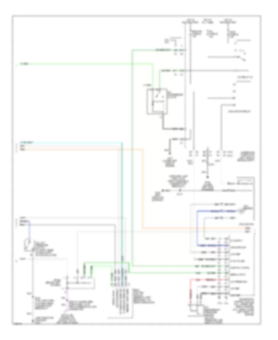
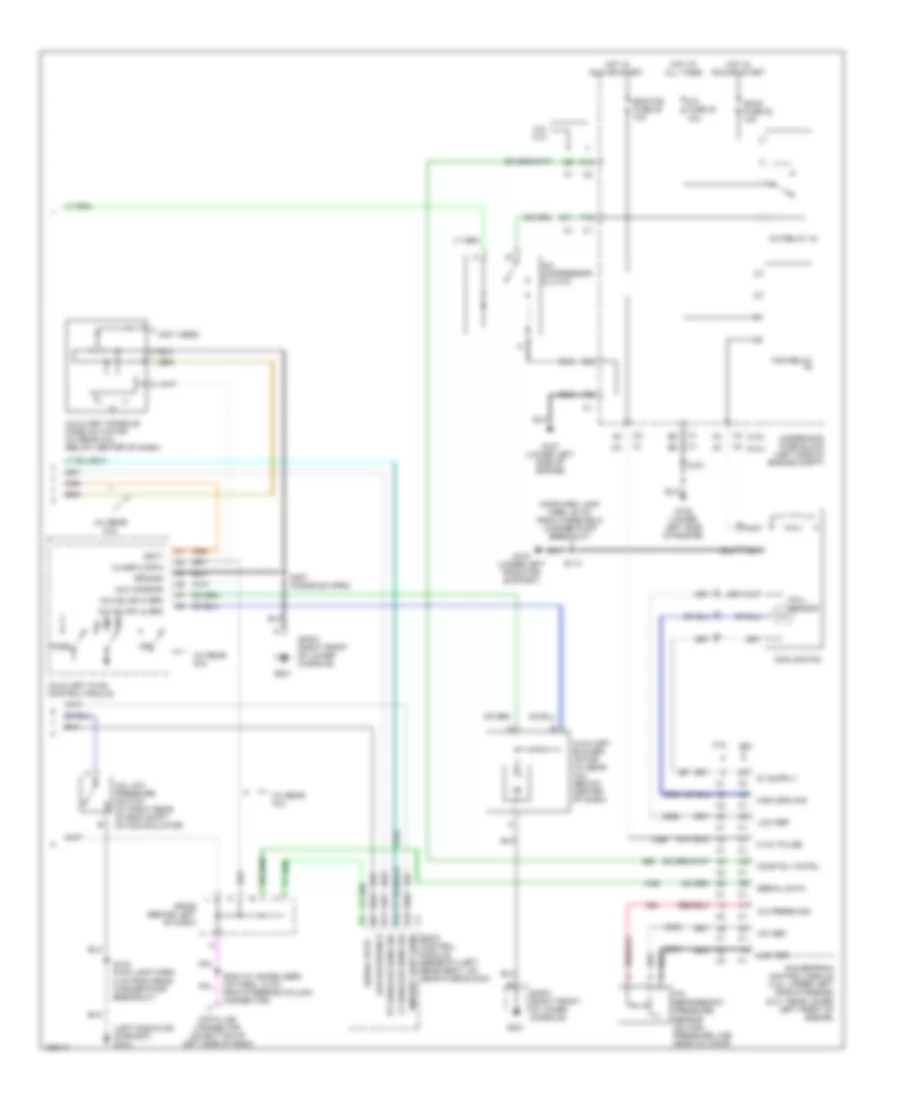
Manual A/C Wiring Diagram, Short Wheel Base (1 of 2) for Chevrolet TrailBlazer 2004
List of elements for Manual A/C Wiring Diagram, Short Wheel Base (1 of 2) for Chevrolet TrailBlazer 2004:
- (below right side of dash) blower motor resistor assembly
- (i/p harn, 15 cm from rec act breakout)
- (i/p harn, 5 cm from mode act breakout)
- 5v ref
- A/c comp status
- A/c low press sw
- A10
- A11
- A12
- Air temp door ctrl
- Air temp dr pos sig
- Air temperature actuator (left) (behind left center of dash)
- Air temperature actuator (right) (behind right center of dash)
- Aux hvac enable
- B10
- B11
- B12
- Battery
- Blower fuse 35 40a
- Blower motor (below right side of dash)
- Blower motor relay
- Class 2
- Def door pos sig
- Defrost actuator (upper left center of dash)
- Defrost door ctrl
- G102 (left side of engine compartment)
- G201
- Ground
- High
- Hot at all times
- Hot in run
- Hvac control module
- Hvac fuse 44 30a
- Hvac i fuse 39 10a
- Hvac-b fuse 36 10a
- Ign 3
- Interior lights system
- Low
- Low ref
- Lps dimming ctrl
- Med1
- Med2
- Med3
- Mode actuator (upper left center of dash)
- Mode door ctrl
- Mode door pos sig
- Off
- Off blwr mtr cntrl
- Rear fuse block (below left rear seat)
- Recirc door cntrl
- Recirulation actuator (upper right side of dash)
- Red
- S202 (i/p harn, 16 cm from strng col conn breakout)
- S211 (i/p harn, 16 cm from sp201)
- S216
- S217
- Solid state
- Sp201 (right front of lower console)
- Sp201 (right frt of lower console)
- Tan
- Under- hood fuse block (left side of engine compt)
- W/ rear a/c
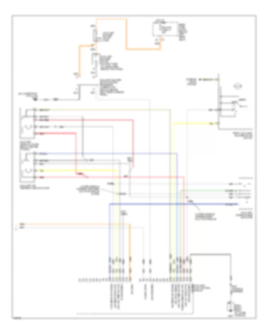
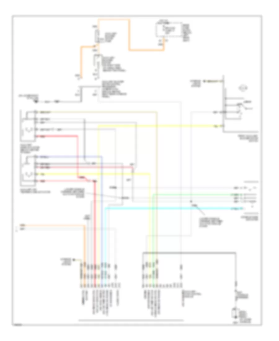
Manual A/C Wiring Diagram, Short Wheel Base (2 of 2) for Chevrolet TrailBlazer 2004
List of elements for Manual A/C Wiring Diagram, Short Wheel Base (2 of 2) for Chevrolet TrailBlazer 2004:
- (4.2l)
- (5.3l)
- (forward lamp harn, 20 cm from windshield washer pump breakout)
- (left radiator support) g103
- (not used)
- (w/ rear a/c)
- +5v ref
- 0-12v pulse
- 4.2l 5.3l
- 5.3l 4.2l
- A/c compressor clutch
- A/c fuse 30 10a
- A/c low pressure switch (at right rear of eng compt, on accumulator)
- A/c press sig
- A/c refrigerant pressure sensor (on high pressure line near a/c comp)
- A/c relay 44
- Aux dr mtr cntrl
- Aux hvac enable
- Auxiliary console mode actuator (w/ rear a/c) (under lower console)
- Auxiliary hvac control module
- Bi lvl
- Comp rly cntrl
- Cooling fan
- D11
- Data link connector (on bottom of left side of dash)
- Eng fan fuse 20 10a
- F10
- F12
- Fan relay
- Floor
- G103 (left radiator support)
- G107 (lower left side of engine)
- G108 (lower left side of engine)
- G201
- Ground
- Hall sensor
- High spd maf
- Hot at all times
- Hot in run or start
- Ign e fuse 22 10a
- Ign voltage
- Lo ref
- Low ref
- Powertrain control module (4.2l: upper left side of engine) (5.3l: near lower left front of engine)
- S101
- S103 (fwd lamp harn, 8 cm from rear washer pump breakout)
- S113
- S232 (w/ immobilizer) (dash harn, 10 cm from steering column connector)
- S307 (console harn)
- Serial data
- Sp201 (right front of lower console)
- Sp205 (behind left of dash)
- Underhood fuse block (left side of engine compt)
- Upper
- W/ rear a/c