AIR CONDITIONING
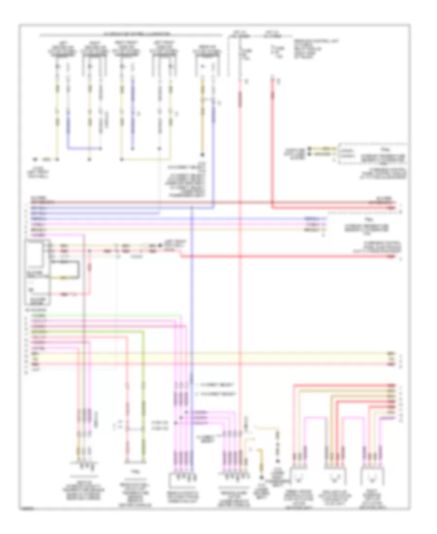
Automatic A/C Wiring Diagram, with 3-Zone (1 of 3) for Mercedes-Benz CLS550 4Matic 2012

List of elements for Automatic A/C Wiring Diagram, with 3-Zone (1 of 3) for Mercedes-Benz CLS550 4Matic 2012:
- (left front footwell) w15/5
- +12v
- 12v
- Air re cir- culation mode button
- Automatic air conditioning control & operating unit
- C13d
- C14m
- C17c
- C18m
- C19i
- C20m
- C21m
- C3m
- C5c
- Can-b h
- Can-b l
- Computer data lines system
- Emissions sensor (right rear of engine compt)
- Evaporator temperature sensor (lower right side of hvac unit)
- Fresh air/ recirculated air flap switchover valve
- Front sam control unit w/ fuse & relay module (left rear of engine compt)
- Fuse 7.5a
- Gnd
- Hot at all times
- Hot w/ engine circuit 87 relay energized
- Interior temperature sensor (right of steering column)
- Left front footwell air outlet temperature sensor
- Left side air outlet temperature sensor (in left side outlet vent)
- Lin
- Lin b8
- Lin kima
- Outside temperature display temperature sensor (behind left side of front fascia)
- Rear window heater button
- Red
- Refrigerant compressor (left front of engine)
- Refrigerant pressure sensor (left front of engine compt)
- Right front footwell air outlet temperature sensor
- Right side air outlet temperature sensor (in right side outlet vent)
- Sig
- Sig li
- Sig re
- Sun sensor (top center of dash)
- W/ magnetic clutch
- W15/2 (left front footwell)
- W15/5 (left front footwell)
- W15/7 (right front footwell)
- X15/5-c2
- X25/2-c1
- X26-c1
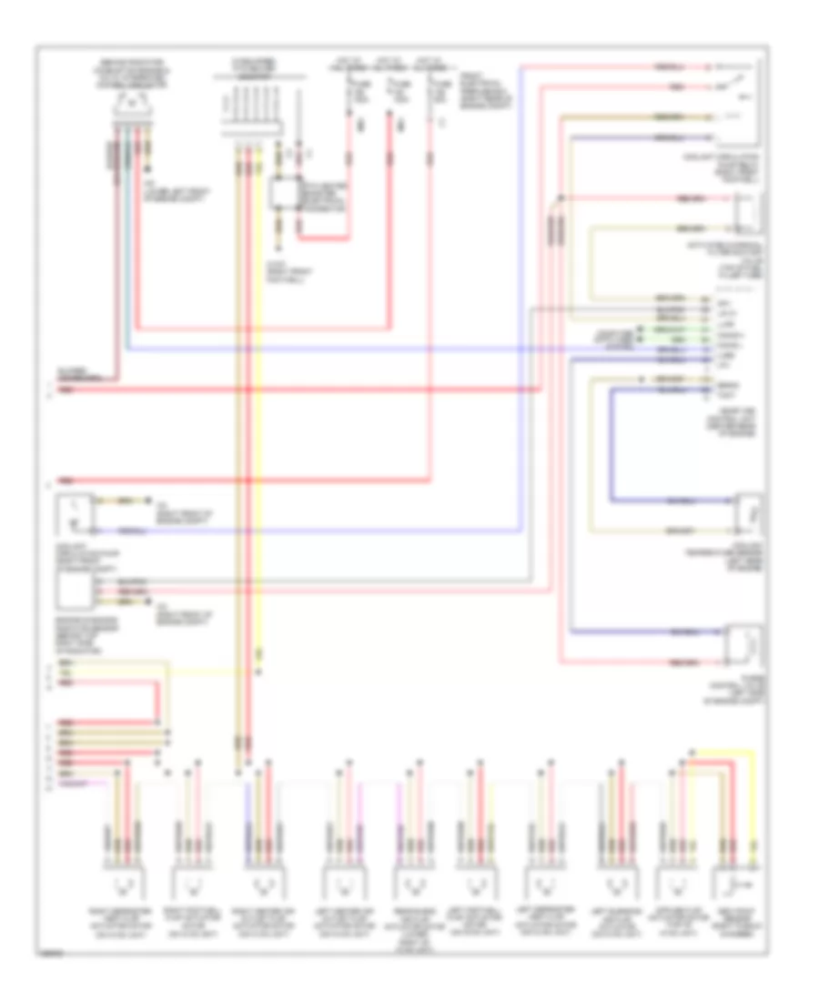
Automatic A/C Wiring Diagram, with 3-Zone (2 of 3) for Mercedes-Benz CLS550 4Matic 2012
List of elements for Automatic A/C Wiring Diagram, with 3-Zone (2 of 3) for Mercedes-Benz CLS550 4Matic 2012:
- (left front footwell) w15/5
- 58d
- 7.5a
- Ac housing
- Blower motor
- Blower regulator
- C3i
- Can-b h
- Can-b l
- Computer data lines system
- Fresh air/air recirculation flap actuator motor (on hvac unit)
- Fuse
- Fuse 7.5a
- Gnd
- Hot at all times
- Interior temperature sensor w/ integrated fan
- Left center air outlet symbol illumination
- Left front side air outlet symbol illumination
- Lin
- Overhead control panel control module (w/ tilting/ sliding roof)
- Overhead control panel electronics (w/o tilting/sliding roof)
- Ram air flap actuator motor (top right of hvac unit)
- Rear air outlet symbol illumination
- Rear automatic air conditioning operating unit
- Rear blower motor (under rear of center console)
- Rear footwell air outlet temperature sensor (rear of center console)
- Rear sam control unit w/ fuse & relay module (right side of trunk)
- Red
- Right blending air flap actuator (on hvac unit)
- Right center air outlet symbol illumination
- Right front side air outlet symbol illumination
- Vehicle interior humidity/ temperature sensor (base of interior rearview mirror)
- W/ air outlet symbol illumination
- W/ direct select
- W/o direct select
- W15/5 (left front footwell)
- W18 (under driver's seat)
- W18 (w/o direct select) w19 (w/ direct select) (w/o direct select: under driver's seat) (w/ direct select: under front passenger's seat)
- W19 (under front passenger's seat)
- X138/1-c2
- X138/1-c3
- X157/1-c2
- X18-c1
- X18-c4
- X83/11-c2
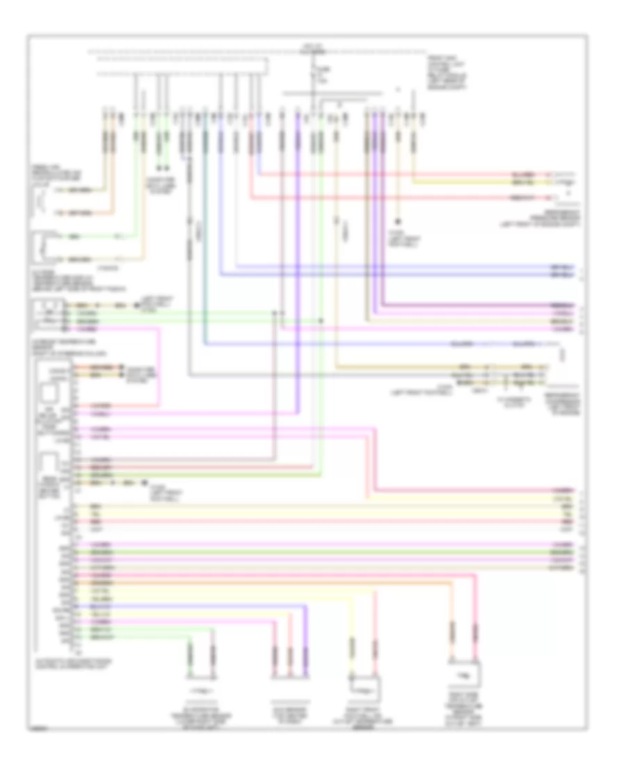
Automatic A/C Wiring Diagram, with 3-Zone (3 of 3) for Mercedes-Benz CLS550 4Matic 2012
List of elements for Automatic A/C Wiring Diagram, with 3-Zone (3 of 3) for Mercedes-Benz CLS550 4Matic 2012:
- (behind radiator) combustion engine & a/c w/ integrated control fan motor
- (if equipped) ptc heater booster
- (on hvac unit)
- Activated charcoal filter shutoff valve (top of fuel filler tube)
- Akv
- Can-e h
- Can-e l
- Computer data lines system
- Coolant circulation pump (right front of engine compt)
- Coolant circulation pump relay (right front footwell)
- Coolant temperature sensor (left rear of engine)
- Dew point sensor (right plenum chamber)
- Diffuse flap actuator motor (top of hvac unit)
- Engine diagnosis radiator sensor (behind top right side of radiator)
- Front electrical prefuse box (right rear of engine compt)
- Fuse 100a
- Fuse 150a
- Fuse 50a
- Hot at all times
- Left blending air flap actuator (on hvac unit)
- Left center air outlet flap actuator motor (on hvac unit)
- Left defroster vent flap actuator motor (on hvac unit)
- Left footwell flap actuator motor (on hvac unit)
- Lin c1
- Llkr
- Lpv
- Lues
- Me-sfi (me) control unit (center rear of engine)
- Mr4
- Mr5
- Ptc heater booster electrical connector
- Purge control valve (left side of engine compt)
- Rear blend air flap actuator motor (lower right of hvac unit)
- Red
- Right center air outlet flap actuator motor (on hvac unit)
- Right defroster vent flap actuator motor
- Right footwell flap actuator motor (on hvac unit)
- Senm3
- Tmot
- W15/7 (right front footwell)
- W2 (right front of engine compt)
- W9 (lower left front of engine compt)
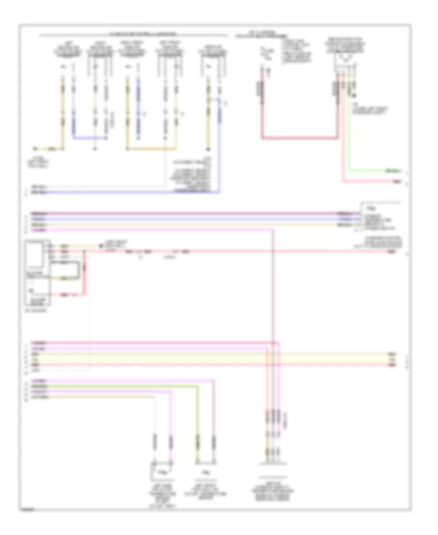
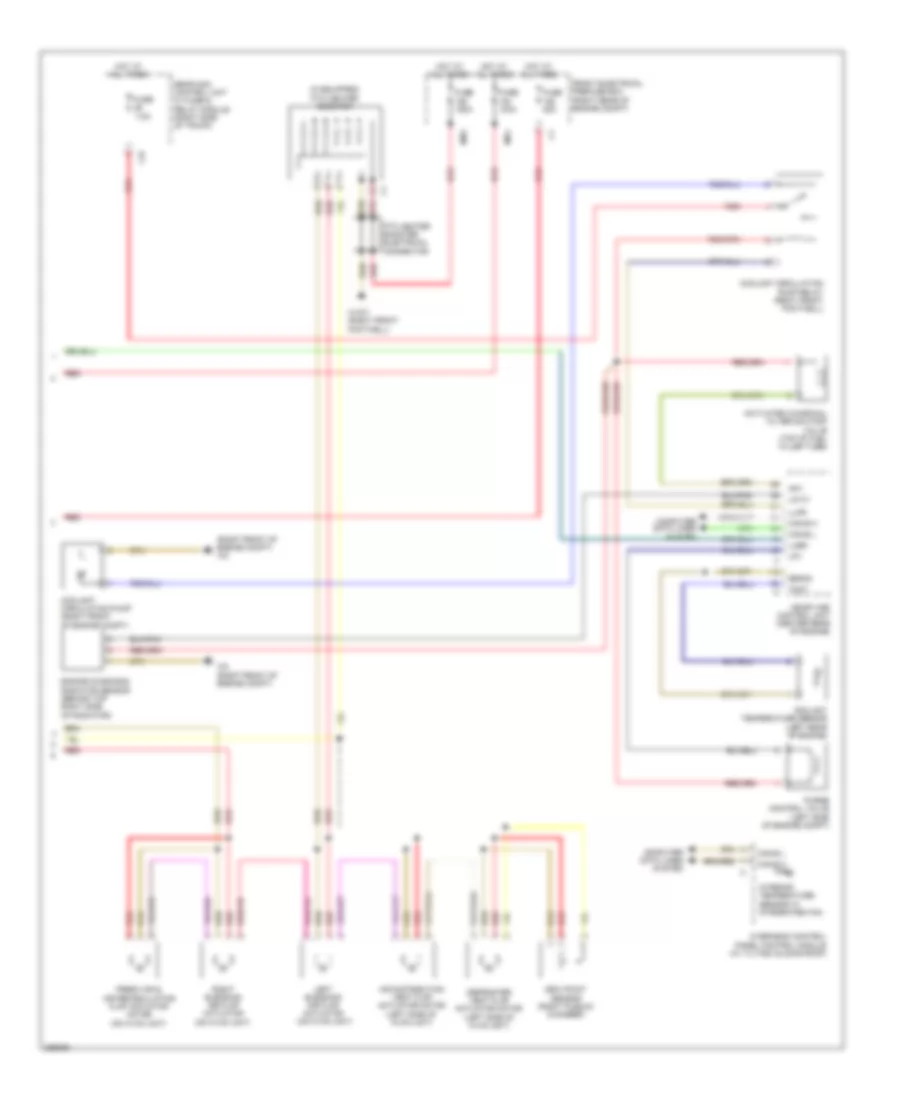
Automatic A/C Wiring Diagram, without 3-Zone (1 of 3) for Mercedes-Benz CLS550 4Matic 2012
List of elements for Automatic A/C Wiring Diagram, without 3-Zone (1 of 3) for Mercedes-Benz CLS550 4Matic 2012:
- (left front footwell) w15/5
- 12v
- 30g
- Air re cir- culation mode button
- Automatic air conditioning control & operating unit
- C13d
- C14m
- C17c
- C18m
- C19i
- C20m
- C21m
- C3m
- C5c
- Can-b h
- Can-b l
- Computer data lines system
- Evaporator temperature sensor (lower right side of hvac unit)
- Fresh air/ recirculated air flap switchover valve
- Front sam control unit w/ fuse/ relay module (left rear of engine compt)
- Fuse 7.5a
- Gnd
- Hot at all times
- Interior temperature sensor (right of steering column)
- Lin b8
- Outside temperature display temperature sensor (behind left side of front fascia)
- Rear window heater button
- Red
- Refrigerant compressor (left front of engine)
- Refrigerant pressure sensor (left front of engine compt)
- Right front footwell air outlet temperature sensor
- Right side air outlet temperature sensor (in right side outlet vent)
- Sig
- Sig li
- Sig re
- Sun sensor (top center of dash)
- W/ magnetic clutch
- W15/2 (left front footwell)
- W15/5 (left front footwell)
- X15/5-c2
- X25/2-c1
- X26-c1
Automatic A/C Wiring Diagram, without 3-Zone (2 of 3) for Mercedes-Benz CLS550 4Matic 2012
List of elements for Automatic A/C Wiring Diagram, without 3-Zone (2 of 3) for Mercedes-Benz CLS550 4Matic 2012:
- (behind radiator) combustion engine & a/c w/ integrated control fan motor
- (left front footwell) w15/5
- Ac housing
- Blower motor
- Blower regulator
- C14m
- Front sam control unit w/ fuse & relay module (left rear of engine compt)
- Fuse 7.5a
- Hot w/ engine circuit 87 relay energized
- Interior temperature sensor w/ integrated fan
- Left center air outlet symbol illumination
- Left front footwell air outlet temperature sensor
- Left front side air outlet symbol illumination
- Left side air outlet temperature sensor (in left outlet vent)
- Overhead control panel electronics (w/o titling/sliding roof)
- Rear air outlet symbol illumination
- Red
- Right center air outlet symbol illumination
- Right front side air outlet symbol illumination
- Vehicle interior humidity/ temperature sensor (base of interior rearview mirror)
- W/ air outlet symbol illumination
- W15/5 (left front footwell)
- W18 (w/o direct select) w19 (w/ direct select) (w/o direct select: under driver's seat) (w/ direct select: under front passenger's seat)
- W9 (lower left front of engine compt)
- X157/1-c2
- X18-c4
- X83/11-c2
Automatic A/C Wiring Diagram, without 3-Zone (3 of 3) for Mercedes-Benz CLS550 4Matic 2012
List of elements for Automatic A/C Wiring Diagram, without 3-Zone (3 of 3) for Mercedes-Benz CLS550 4Matic 2012:
- (if equipped) ptc heater booster
- (right front of engine compt) w2
- 7.5a
- Activated charcoal filter shutoff valve (top of fuel filler tube)
- Air distribution vent flap actuator motor (left side of hvac unit)
- Akv
- C3i
- Can-b h
- Can-b l
- Can-e h
- Can-e l
- Computer data lines system
- Coolant circulation pump (right front of engine compt)
- Coolant circulation pump relay (right front footwell)
- Coolant temperature sensor (left rear of engine)
- Defroster vent flap actuator motor (left side of hvac unit)
- Dew point sensor (right plenum chamber)
- Engine diagnosis radiator sensor (behind top right side of radiator)
- Fresh air & air recirculating flap actuator motor (on hvac unit)
- Front electrical prefuse box (right rear of engine compt)
- Fuse
- Fuse 100a
- Fuse 150a
- Fuse 50a
- Hot at all times
- Interior temperature sensor w/ integrated fan
- Left blending air flap actuator (on hvac unit)
- Lin c1
- Llkr
- Lpv
- Lues
- Me-sfi (me) control unit (center rear of engine)
- Mr4
- Mr5
- Overhead control panel control module (w/ tilting/ sliding roof)
- Ptc heater booster electrical connector
- Purge control valve (left side of engine compt)
- Rear sam control unit w/ fuse & relay module (right side of trunk)
- Red
- Right blending air flap actuator (on hvac unit)
- Senm3
- Tmot
- W15/7 (right front footwell)
- W2 (right front of engine compt)