AIR CONDITIONING
Air Conditioning Wiring Diagrams for Mercedes-Benz E320 1996

List of elements for Air Conditioning Wiring Diagrams for Mercedes-Benz E320 1996:
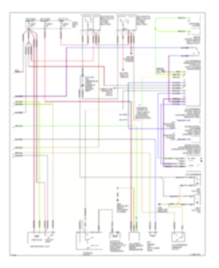
Air Conditioning Wiring Diagrams (1 of 2) for Mercedes-Benz E320 1996
List of elements for Air Conditioning Wiring Diagrams (1 of 2) for Mercedes-Benz E320 1996:
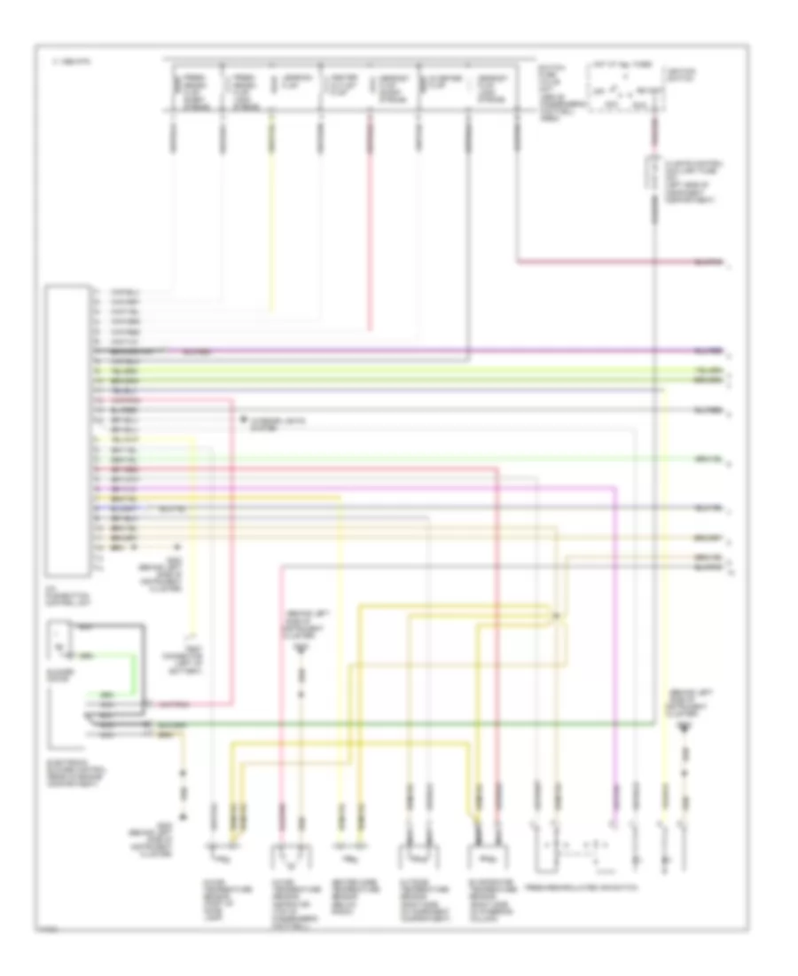
Air Conditioning Wiring Diagrams (2 of 2) for Mercedes-Benz E320 1996
List of elements for Air Conditioning Wiring Diagrams (2 of 2) for Mercedes-Benz E320 1996: