AIR CONDITIONING
A/C Wiring Diagram for Subaru Impreza Brighton 1997

List of elements for A/C Wiring Diagram for Subaru Impreza Brighton 1997:
- (left side of engine compartment)
- (right radiator support)
- (right side
- A/c relay holder
- A/c switch
- Acc
- Air conditioner fuse 10a
- Air conditioning cut relay (right side of firewall)
- Air conditioning relay (in a/c relay holder)
- Blower motor
- Blower motor relay (behind left side of dash)
- Blower motor resistor (behind right side of dash)
- Clutch
- Compressor
- Diode (a/c) (behind left side of dash)
- E11
- Engine control module (under passenger floorboard)
- Evaporation thermoswitch (behind right side of dash)
- F27
- Fan switch
- Fuse 10a
- Fuse 20 15a
- Fuse 20a
- Fuse 21 15a
- Fuse and relay box
- G109
- G201
- Hot at all times
- Hot in on or start
- I17
- I30
- Ignition switch
- Interior lights system
- Main fan motor
- Main fan relay
- Mode control panel
- Nca
- Of dash)
- Off
- Pressure switch
- Run
- Start
- Sub fan motor
- Sub-fan relay (in a/c relay holder)
- Thermal protector
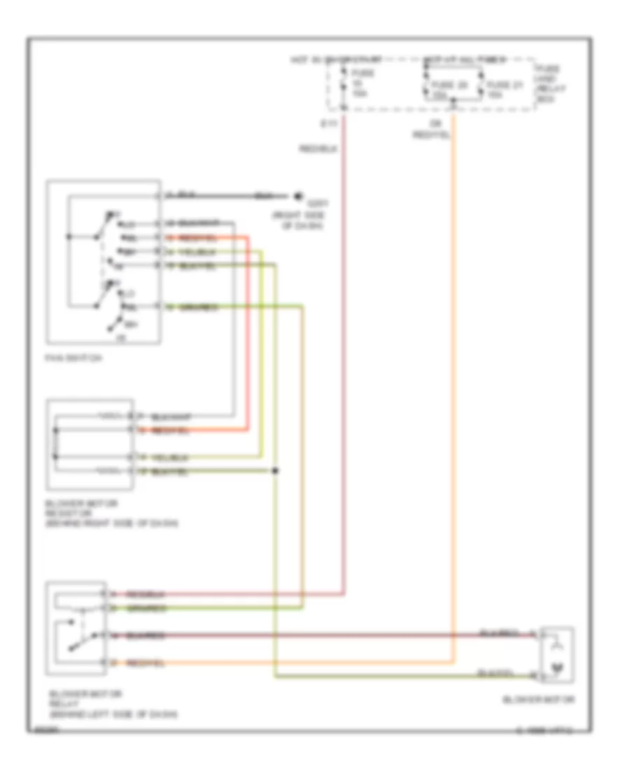
Heater Wiring Diagram for Subaru Impreza Brighton 1997
List of elements for Heater Wiring Diagram for Subaru Impreza Brighton 1997:
- (right side
- Blower motor
- Blower motor relay (behind left side of dash)
- Blower motor resistor (behind right side of dash)
- C 1995 vftc
- E11
- Fan switch
- Fuse 10a
- Fuse 20 15a
- Fuse 21 15a
- Fuse and relay box
- G201
- Hot at all times
- Hot in on or start
- Of dash)
- Off