AIR CONDITIONING
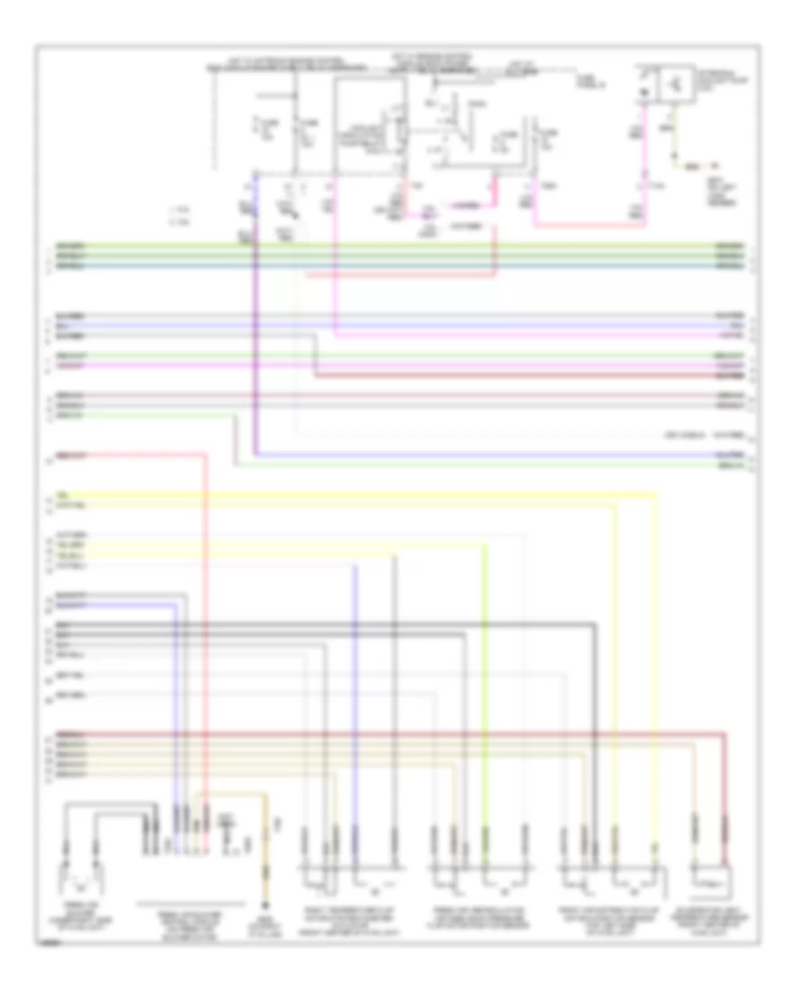
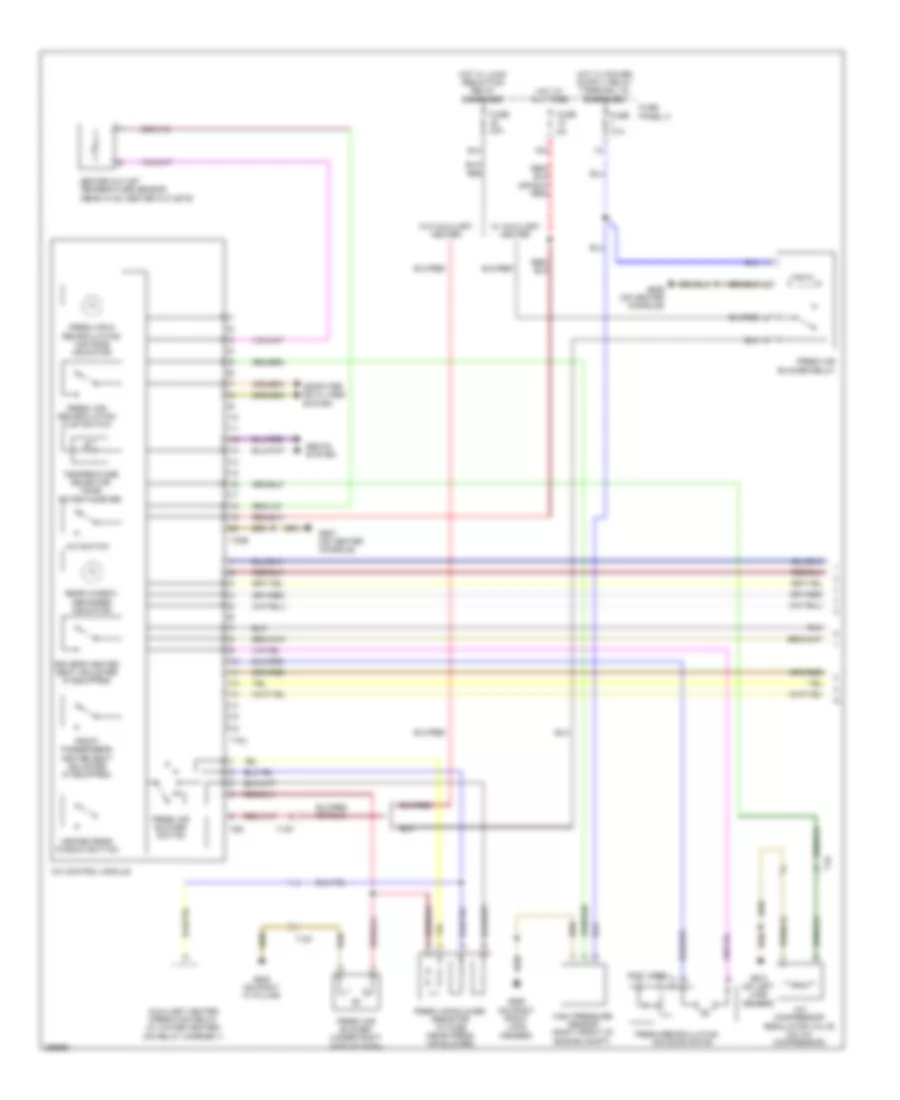
Automatic A/C Wiring Diagram (1 of 3) for Volkswagen CC VR6 4Motion 2011

List of elements for Automatic A/C Wiring Diagram (1 of 3) for Volkswagen CC VR6 4Motion 2011:
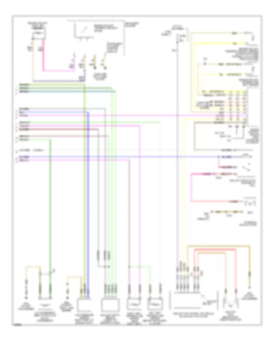
Automatic A/C Wiring Diagram (2 of 3) for Volkswagen CC VR6 4Motion 2011
List of elements for Automatic A/C Wiring Diagram (2 of 3) for Volkswagen CC VR6 4Motion 2011:
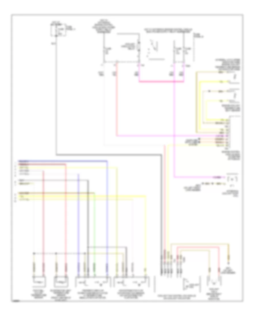
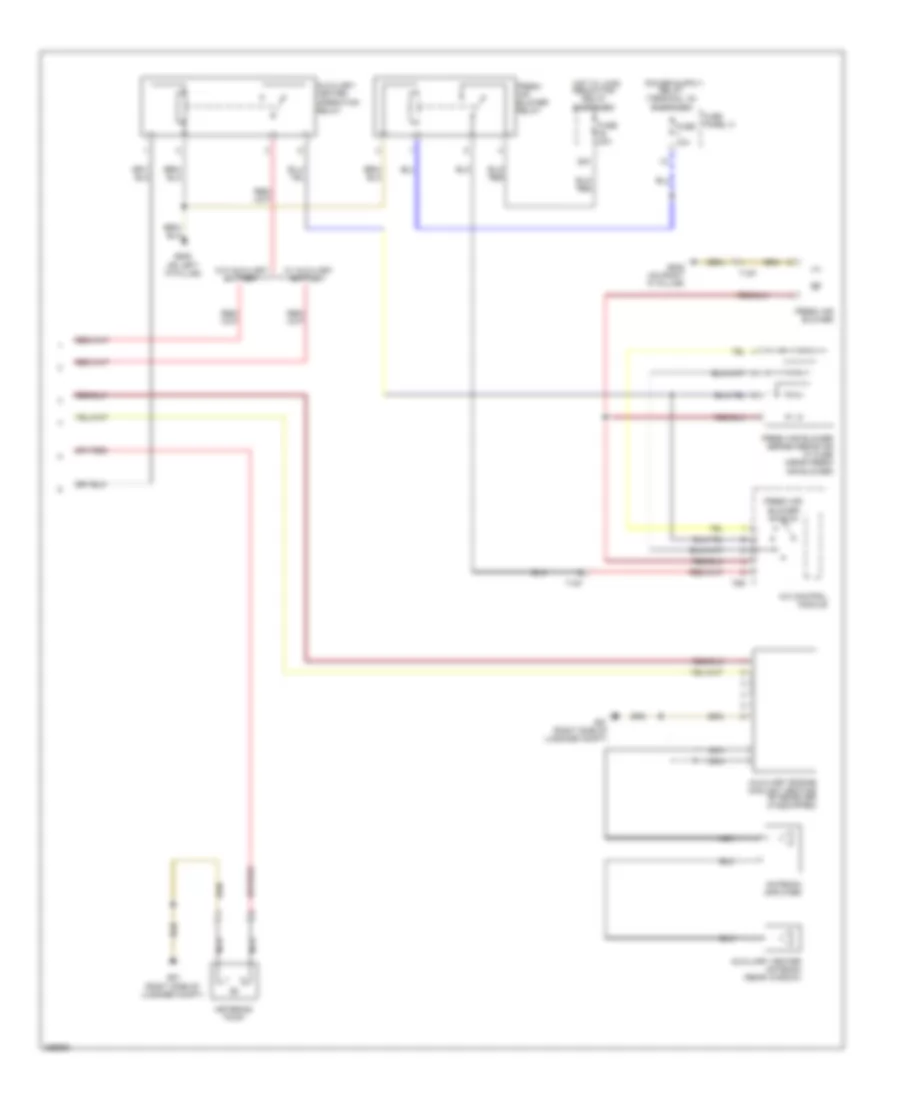
Automatic A/C Wiring Diagram (3 of 3) for Volkswagen CC VR6 4Motion 2011
List of elements for Automatic A/C Wiring Diagram (3 of 3) for Volkswagen CC VR6 4Motion 2011:
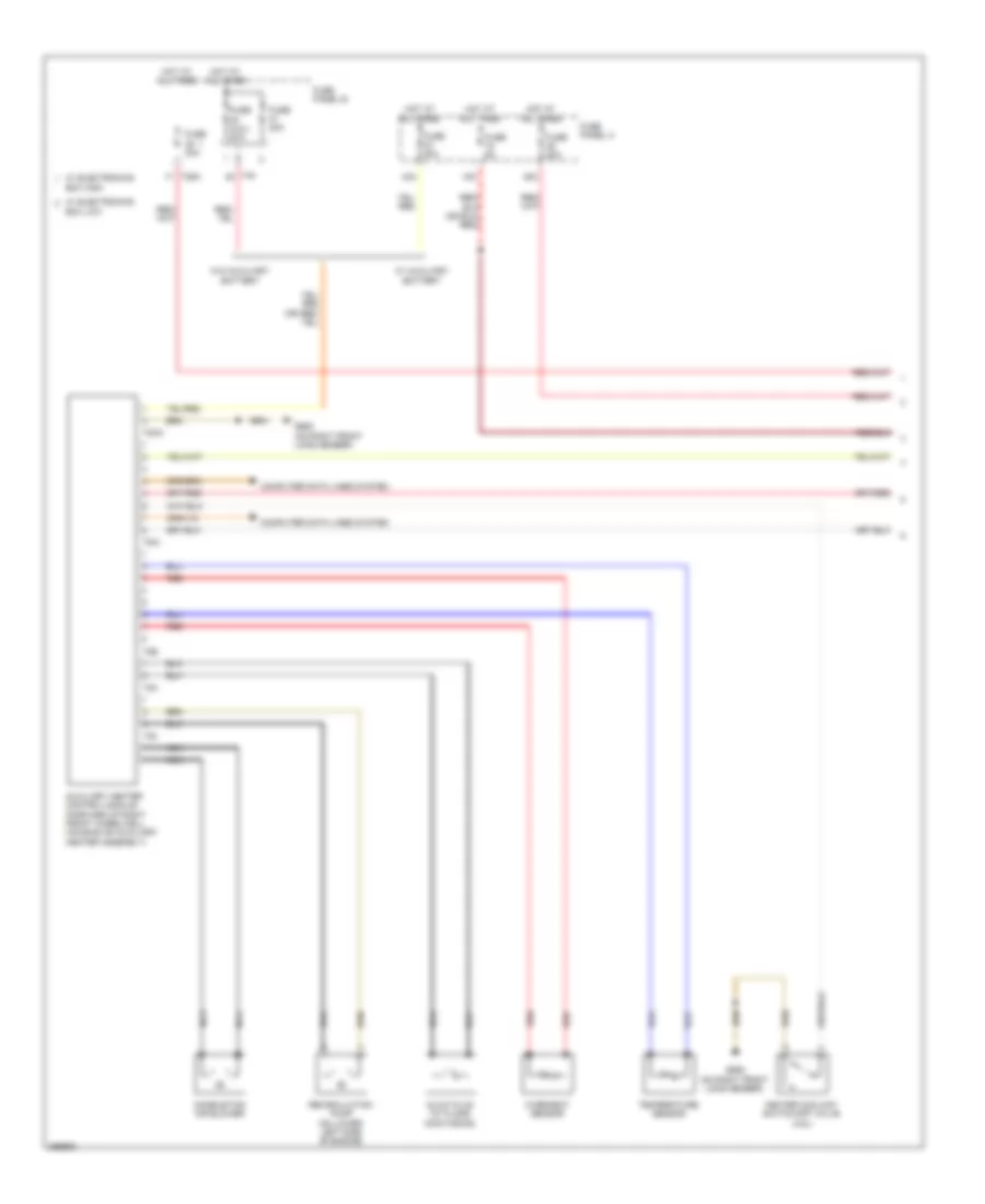
Auxiliary Heater Wiring Diagram (1 of 2) for Volkswagen CC VR6 4Motion 2011
List of elements for Auxiliary Heater Wiring Diagram (1 of 2) for Volkswagen CC VR6 4Motion 2011:
Auxiliary Heater Wiring Diagram (2 of 2) for Volkswagen CC VR6 4Motion 2011
List of elements for Auxiliary Heater Wiring Diagram (2 of 2) for Volkswagen CC VR6 4Motion 2011:
Manual A/C Wiring Diagram (1 of 2) for Volkswagen CC VR6 4Motion 2011
List of elements for Manual A/C Wiring Diagram (1 of 2) for Volkswagen CC VR6 4Motion 2011:
Manual A/C Wiring Diagram (2 of 2) for Volkswagen CC VR6 4Motion 2011
List of elements for Manual A/C Wiring Diagram (2 of 2) for Volkswagen CC VR6 4Motion 2011: