ANTI-LOCK BRAKES
Anti-lock Brakes Wiring Diagram, Premium Model (1 of 2) for Acura 3.2CL 2003

List of elements for Anti-lock Brakes Wiring Diagram, Premium Model (1 of 2) for Acura 3.2CL 2003:
- (at center rear of engine) g101
- (at left side of engine compt) test tachometer connector
- (below left side of dash) junction connector c304
- (not used)
- A/t pos sw
- A10
- A11
- A12
- A13
- A14
- A15
- A16
- A17
- A18
- A19
- A20
- A21
- A22
- A23
- A24
- A25
- A26
- A29
- Abs ind
- Abs indicator circuit
- Abs pump ctrl
- Abs/tcs control unit (behind right kick panel)
- B10
- B11
- B12
- B13
- B14
- B15
- B16
- B4
- Brake pedal position switch (at top of brake pedal arm)
- Brake sw in
- C10
- C11
- C12
- C17
- C18
- C4
- Canada
- Computer data lines system
- Cruise control/ tcs switch
- Driver's multiplex control unit
- Driver's under dash fuse/ relay box (behind left side of dash)
- Driver's underdash fuse/relay box (behind left side of dash)
- Drl control unit (behind left side of dash)
- E16
- E17
- Engine retard
- F13
- F14
- Fail-safe rly
- Fl in
- Fl out
- Flw (+)
- Flw (-)
- Fr in
- Fr out
- Frw (+)
- Frw (-)
- Fuse 4 7.5a
- Fuse 47 20a
- Fuse 6 15a
- Fuse 9 7.5a
- G402 (above right kick panel)
- G403 (above right kick panel)
- G501 (behind left center of dash)
- Gauge assembly
- Ground
- Hot at all times
- Hot in on
- Hot in on or start
- Ign in
- J/c c452 (below left side of dash)
- J10
- J12
- Left front wheel speed sensor
- Left rear wheel speed sensor
- M10
- M15
- Main circuit
- Ncl
- Ncr
- Nol
- Nor
- Park brake
- Parking brake and brake system ind
- Passenger's underdash fuse/relay box (behind right kick panel)
- Pnk
- Powertrain control module (below center of dash)
- Pump mtr check
- Ref voltage
- Retard req
- Right front wheel speed sensor
- Right rear wheel speed sensor
- Rl in
- Rl out
- Rlw (+)
- Rlw (-)
- Rpm in
- Rpm out
- Rr in
- Rr out
- Rrw (+)
- Rrw (-)
- Scan in/out
- Svc check
- Tcs 1
- Tcs 2
- Tcs ind
- Tcs per in
- Tcs per out
- Tcs rly ctrl
- Tcs switch in
- Throttle pos
- Underhood fuse/relay box (on right side of firewall)
- Usa
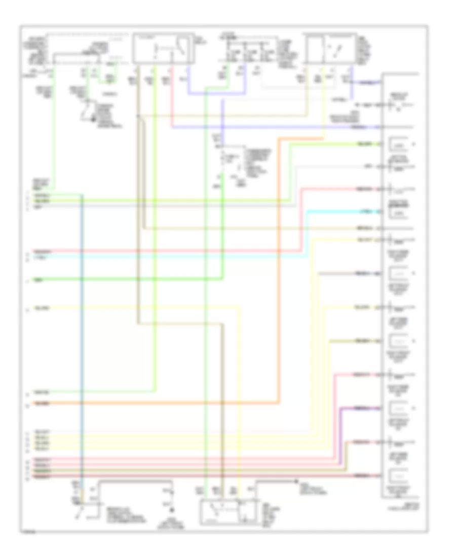
Anti-lock Brakes Wiring Diagram, Premium Model (2 of 2) for Acura 3.2CL 2003
List of elements for Anti-lock Brakes Wiring Diagram, Premium Model (2 of 2) for Acura 3.2CL 2003:
- (not used)
- Abs fail-safe relay (in abs relay box)
- Abs pump motor
- Abs pump motor relay (in abs relay box)
- Abs/tcs modulator unit
- B15
- Brake fluid level switch (integral to brake fluid reservoir cap)
- Canada
- Driver's multiplex control unit
- Driver's underdash fuse/relay box (behind left side of dash)
- Fuse 14 7.5a
- Fuse 20a
- Fuse 30a
- G18
- G202 (left front shock tower)
- G203 (front of right front fender)
- G302 (left front shock tower)
- Hot at all times
- K14
- Left front solenoid (in)
- Left front solenoid (out)
- Left rear solenoid (in)
- Left rear solenoid (out)
- Left tcs solenoids
- Parking brake switch (top of parking brake pedal)
- Passenger's underdash fuse/relay box (behind right kick panel)
- Right front solenoid (in)
- Right front solenoid (out)
- Right rear solenoid (in)
- Right rear solenoid (out)
- Right tcs solenoids
- Tcs relay
- Under hood fuse/ relay box (on right side of firewall)
- Usa
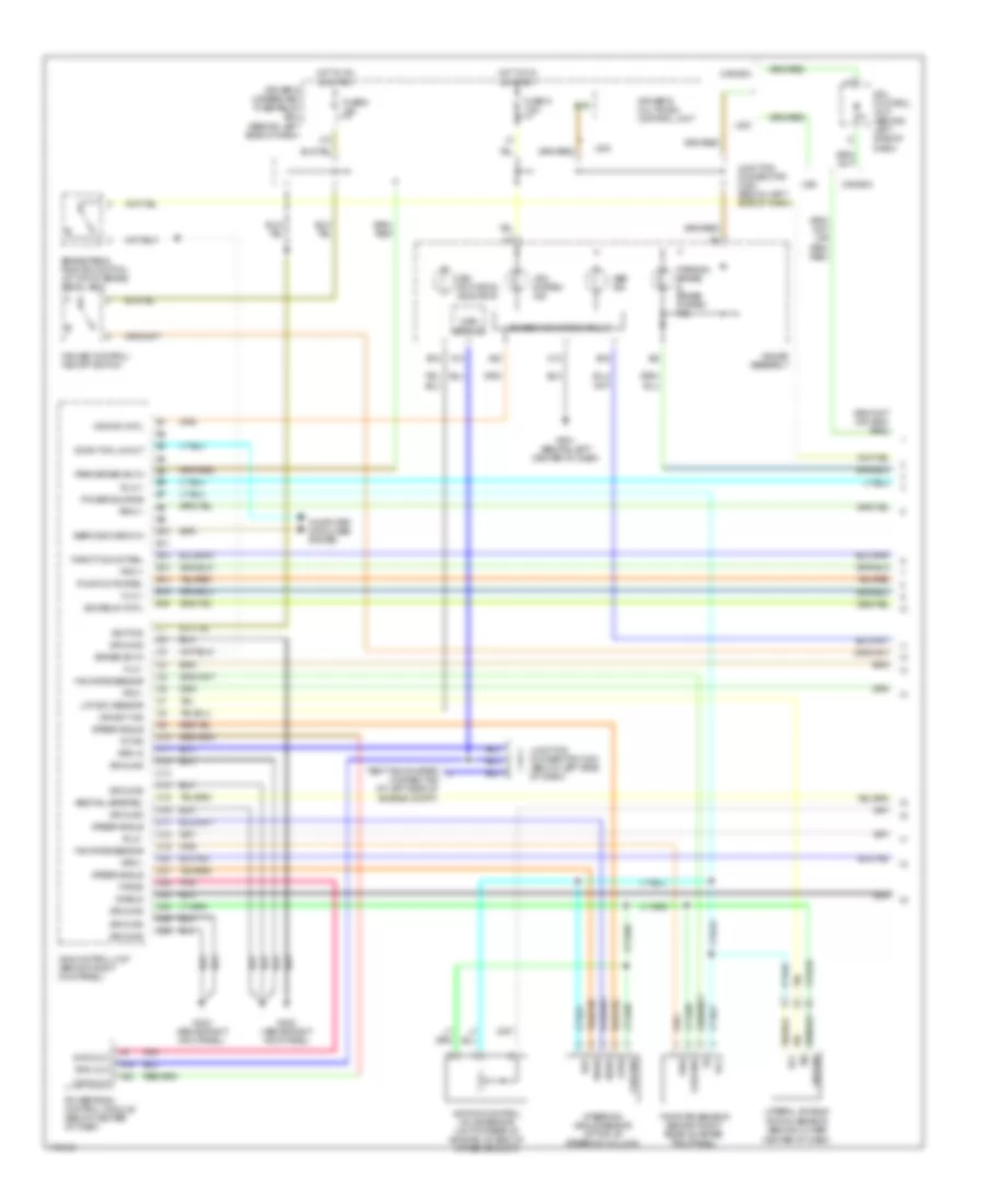
Anti-lock Brakes Wiring Diagram, Type S A/T (1 of 3) for Acura 3.2CL 2003
List of elements for Anti-lock Brakes Wiring Diagram, Type S A/T (1 of 3) for Acura 3.2CL 2003:
- A13
- A19
- A20
- A22
- Abs fail-safe rel
- Abs ind
- B10
- B11
- B12
- B13
- B14
- B15
- B16
- B4
- Brake pedal position switch (at top of brake pedal arm)
- Brake sw in
- C10
- C11
- C12
- C13
- C14
- C15
- C16
- C17
- C18
- C19
- C20
- C21
- C22
- C23
- C24
- C25
- C26
- C4
- Canada
- Center of dash)
- Computer data lines system
- Cruise control/ vsa off switch
- Data out
- Diag
- Driver's multiplex control unit
- Driver's underdash fuse/relay box (behind left side of dash)
- Drl control unit (behind left side of dash)
- Flw +
- Flw -
- Frw +
- Frw -
- Fuse 6 15a
- Fuse 9 7.5a
- G402 (above right kick panel)
- G403 (above right kick panel)
- G501 (behind left center of dash)
- Gauge assembly
- Ground
- Hot in on or start
- Ignition
- J12
- Junction connector c304 (below left side of dash)
- Junction connector c452 (below left side of dash)
- Lat acc sensor
- Lateral accele- ration sensor (behind lower
- Main circuit
- Park brake sw in
- Parking brake & brake system ind
- Pnk
- Power source
- Powertrain control module (below center of dash)
- Pump motor rel
- Ref
- Rlw +
- Rlw -
- Rpm in
- Rpm out
- Rrw +
- Rrw -
- Scan tool in/out
- Sdiag
- Service check in
- Shield
- Steer angle
- Steering angle sensor (at top of steering column)
- Stra
- Tcrxd
- Tctxd
- Test tachometer connector (at left side of engine compt)
- Throttle mot rel
- Usa
- Vcc
- Vsa act ind
- Vsa activation indicator
- Vsa control unit (brhind right kick panel)
- Vsa ind cntl
- Vsa relay cntl
- Vsa system ind
- Vsa/abs indicator circuit
- Vsa/tcs control valve sensor (on top rear of engine, on end of intake air duct)
- Yaw rate sensor
- Yaw rate sensor (behind right rear quarter trim panel)
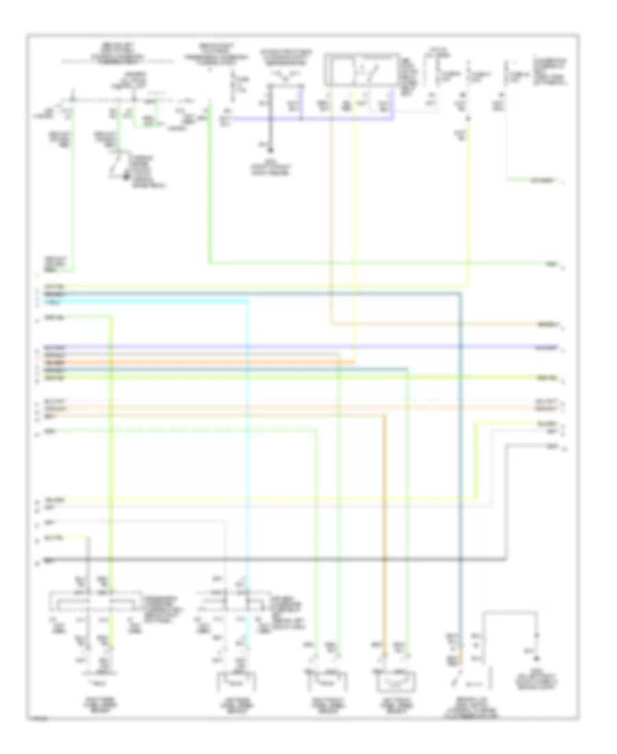
Anti-lock Brakes Wiring Diagram, Type S A/T (2 of 3) for Acura 3.2CL 2003
List of elements for Anti-lock Brakes Wiring Diagram, Type S A/T (2 of 3) for Acura 3.2CL 2003:
- (at right front side of engine compt) vsa pump motor
- (behind left side of dash) driver's underdash fuse/relay box
- (behind right kick panel) passenger's underdash fuse/relay box
- (not used)
- Abs pump motor relay (in abs relay box)
- B11
- B15
- B16
- Brake fluid level switch (integral to brake fluid reservoir cap)
- C17
- C18
- Canada
- D2 d2
- Driver's multiplex control unit
- Driver's underdash fuse/relay box (behind left side of dash)
- F13
- F14
- Fuse 47 20a
- Fuse 48 20a
- Fuse 50 30a
- Fuse 7.5a
- G18
- G203 (front of right front fender)
- G302 (on left front shock tower, in engine compt)
- Hot at all times
- J10
- K14
- L9 k14
- Left front wheel speed sensor
- Left rear wheel speed sensor
- M10
- Parking brake switch (top of parking brake pedal)
- Passenger's underdash fuse/relay box (behind right kick panel)
- Right front wheel speed sensor
- Right rear wheel speed sensor
- Underhood fuse/relay box (right side of firewall)
- Usa canada
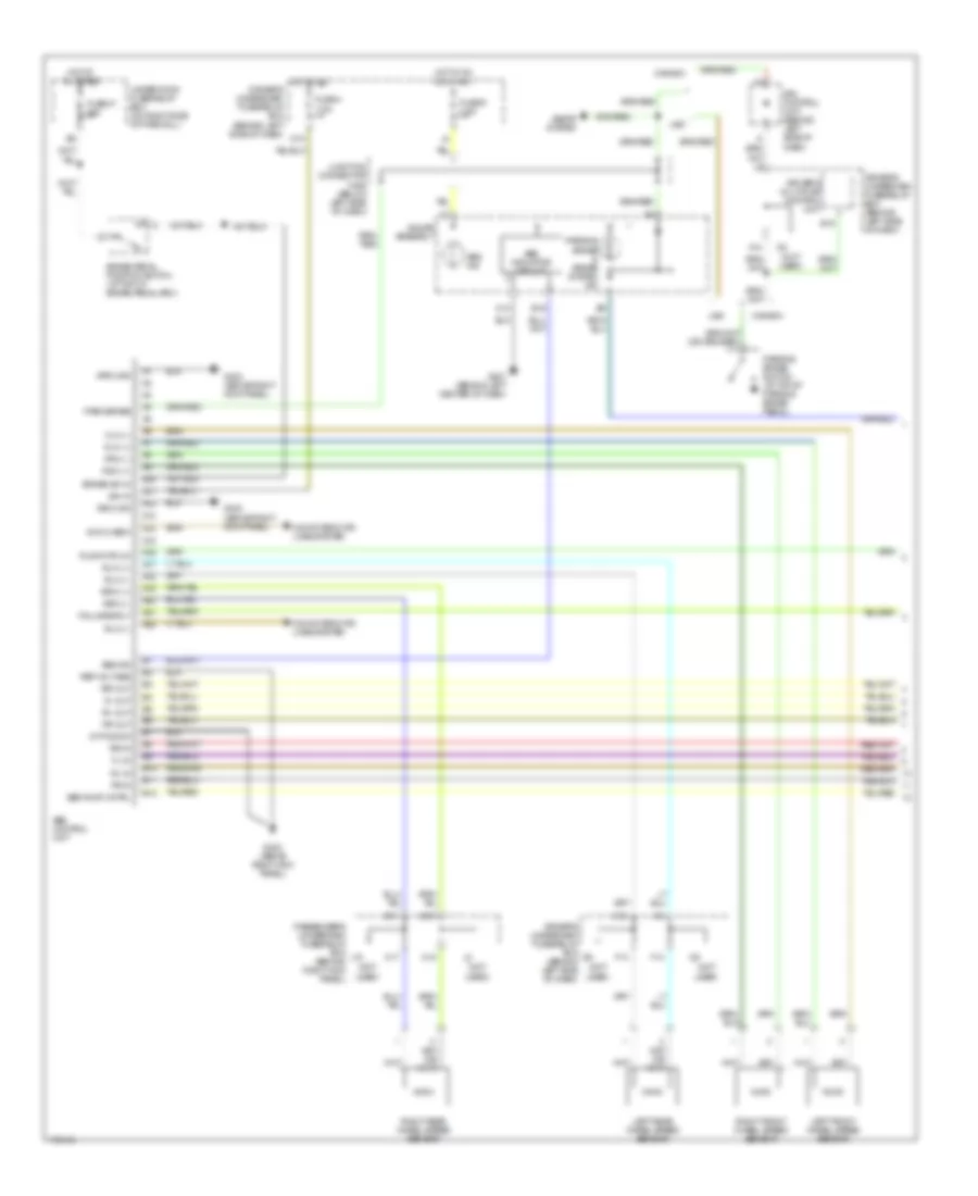
Anti-lock Brakes Wiring Diagram, Type S A/T (3 of 3) for Acura 3.2CL 2003
List of elements for Anti-lock Brakes Wiring Diagram, Type S A/T (3 of 3) for Acura 3.2CL 2003:
- (front of right front fender) g201
- (top rear of eng, on end of intake air duct)
- A10
- A11
- A12
- A13
- A14
- A15
- A16
- A17
- A18
- A19
- A20
- A21
- A22
- Abs fail-safe relay (in abs relay box)
- Abs ind ctrl
- Auxiliary fuse holder (behind right end of dash)
- Fl dump sol
- Fl-in
- Fl-out
- Fr dump sol
- Fr-in
- Fr-out
- G202 (on right front shock tower, in engine compt)
- G403 (above right kick panel)
- Ground
- Hot at all times
- Left front dump solenoid
- Left front solenoid (in)
- Left front solenoid (out)
- Left rear solenoid (in)
- Left rear solenoid (out)
- M(+)
- M(-)
- Pnk
- Power
- Pump motor
- Red
- Right front dump solenoid
- Right front solenoid (in)
- Right front solenoid (out)
- Right rear solenoid (in)
- Right rear solenoid (out)
- Rl-in
- Rl-out
- Rr-in
- Rr-out
- Th2
- Vsa control unit (behind right kick panel)
- Vsa fuse 20a
- Vsa modulator unit
- Vsa off sw
- Vsa-tcs control valve actuator relay
- Vsa-tcs relay
- Vsa/tcs control valve actuator
Anti-lock Brakes Wiring Diagram, Type S M/T (1 of 2) for Acura 3.2CL 2003
List of elements for Anti-lock Brakes Wiring Diagram, Type S M/T (1 of 2) for Acura 3.2CL 2003:
- (not used)
- A/t pos sw
- A10
- A11
- A12
- A13
- A14
- A15
- A16
- A17
- A18
- A19
- A20
- A21
- A22
- Abs control unit
- Abs ind
- Abs indicator circuit
- Abs pump cntrl
- B10
- B11
- B12
- B15
- B16
- B4
- Brake pedal position switch (at top of brake pedal arm)
- Brake sw in
- C10
- C17
- C18
- Canada
- Computer data lines system
- Driver's multiplex control unit
- Driver's underdash fuse/relay box (behind left side of dash)
- Drl control unit (behind left side of dash)
- F13
- F14
- Fail-safe rly
- Fl-in
- Fl-out
- Flw (+)
- Flw (-)
- Fr-in
- Fr-out
- Frw (+)
- Frw (-)
- Fuse 4 7.5a
- Fuse 47 20a
- Fuse 9 7.5a
- G402 (above right kick panel)
- G403 (above right kick panel)
- G501 (behind left center of dash)
- Gauge assembly
- Ground
- Hot at all times
- Hot in on
- Hot in on or start
- Ign in
- J10
- Junction connector c452 (below left side of dash)
- K14
- Left front wheel speed sensor
- Left rear wheel speed sensor
- M10
- M15
- Park brake
- Parking brake & brake system ind
- Parking brake switch (at top of parking brake pedal)
- Passenger's underdash fuse/relay box (behind right kick panel)
- Pump mtr ck
- Ref voltage
- Right front wheel speed sensor
- Right rear wheel speed sensor
- Rl-in
- Rl-out
- Rlw (+)
- Rlw (-)
- Rr-in
- Rr-out
- Rrw (+)
- Rrw (-)
- Seats system
- Svc check
- Underhood fuse/relay box (on right side of firewall)
- Usa
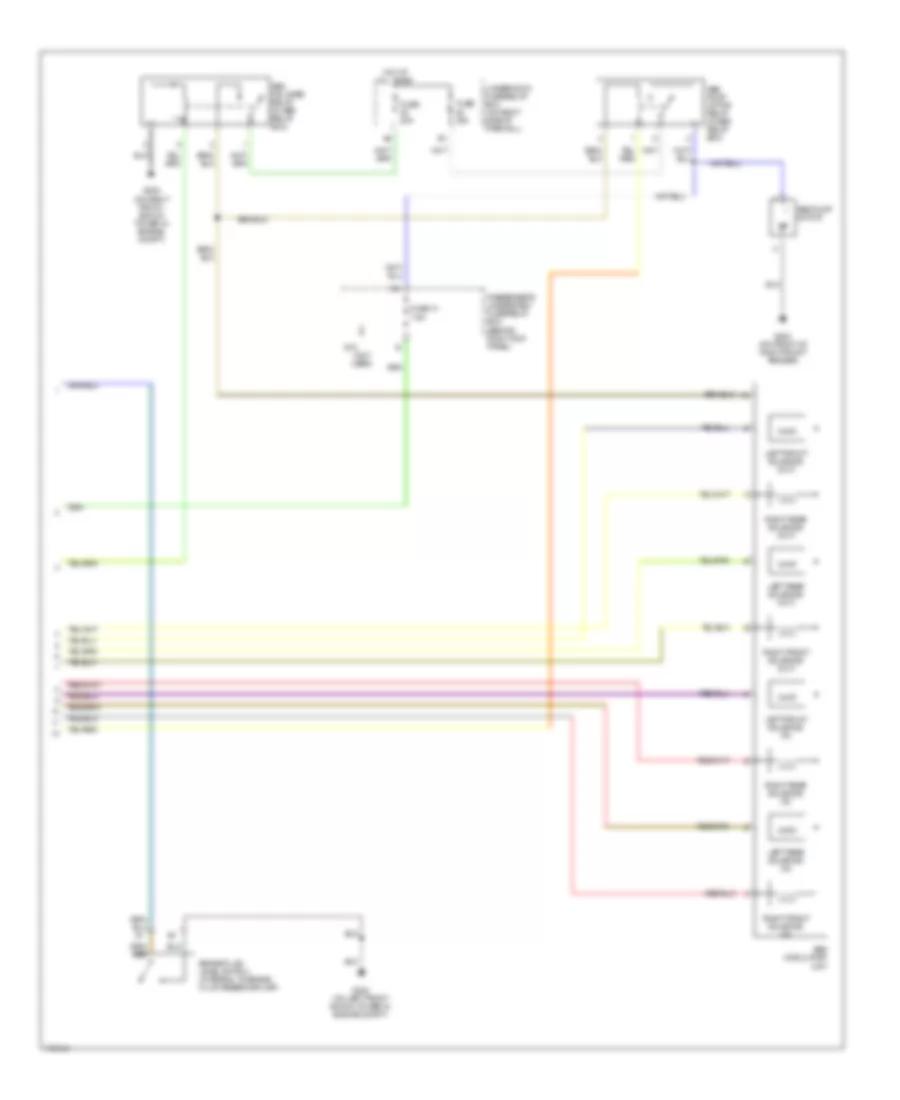
Anti-lock Brakes Wiring Diagram, Type S M/T (2 of 2) for Acura 3.2CL 2003
List of elements for Anti-lock Brakes Wiring Diagram, Type S M/T (2 of 2) for Acura 3.2CL 2003:
- Abs fail-safe relay (in abs relay box)
- Abs modulator unit
- Abs pump motor
- Abs pump motor relay (in abs relay box)
- Brake fluid level switch (integral to brake fluid reservoir cap)
- Fuse 14 7.5a
- Fuse 20a
- Fuse 30a
- G18 (not used)
- G202 (on right front shock tower in engine compt)
- G203 (on front of right front fender)
- G302 (on left front shock tower in engine compt)
- Hot at all times
- Left front solenoid (in)
- Left front solenoid (out)
- Left rear solenoid (in)
- Left rear solenoid (out)
- Passenger's underdash fuse/relay box (behind right kick panel)
- Right front solenoid (in)
- Right front solenoid (out)
- Right rear solenoid (in)
- Right rear solenoid (out)
- Underhood fuse/relay box (on right side of firewall)