ANTI-LOCK BRAKES
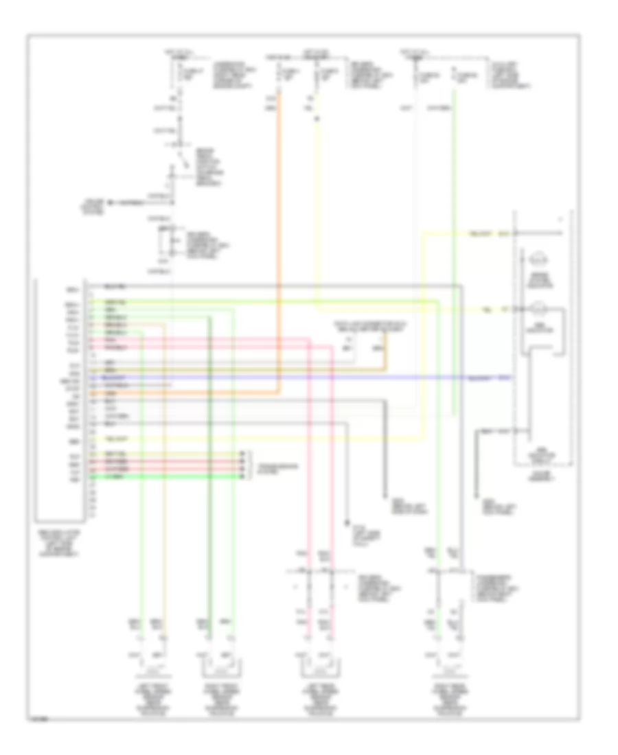
Anti-lock Brakes Wiring Diagram for Acura MDX Touring 2002
List of elements for Anti-lock Brakes Wiring Diagram for Acura MDX Touring 2002:
- Abs ind
- Abs indicator
- Abs indicator circuit
- Abs modulator control unit (left side of engine compartment)
- Auxiliary fuse box (left side of engine compartment)
- B15
- B16
- Bat
- Brake pedal position switch (on brake pedal bracket)
- Brake system indicator
- C10
- Cruise control system
- D15
- D16
- Data link connector (dlc) (below center of dash)
- Dlc
- Driver's underdash fuse/relay box (behind left kick panel)
- Ebd
- F13
- F14
- Flp
- Flw+
- Flw-
- Frp
- Frw+
- Frw-
- Fuse 4 7.5a
- Fuse 47 20a
- Fuse 62 20a
- Fuse 63 40a
- Fuse 9 10a
- G116 (left side of safety wall)
- G200 (behind left kick panel)
- G202 (behind left side of dash)
- Gauge assembly
- Gnd1
- Gnd2
- Hot at all times
- Hot in on
- Hot in on or start
- I11
- Ig2
- Left front wheel speed sensor (rear suspension knuckle)
- Left rear wheel speed sensor (rear suspension knuckle)
- M20
- Passenger's underdash fuse/relay box (behind right kick panel)
- Pnk
- Right front wheel speed sensor (rear suspension knuckle)
- Right rear wheel speed sensor (rear suspension knuckle)
- Rlp
- Rls+
- Rls-
- Rrp
- Rrw+
- Rrw-
- Scs
- Stop
- Transmissions system
- Underhood fuse/relay box (right rear corner of engine compt)
 English