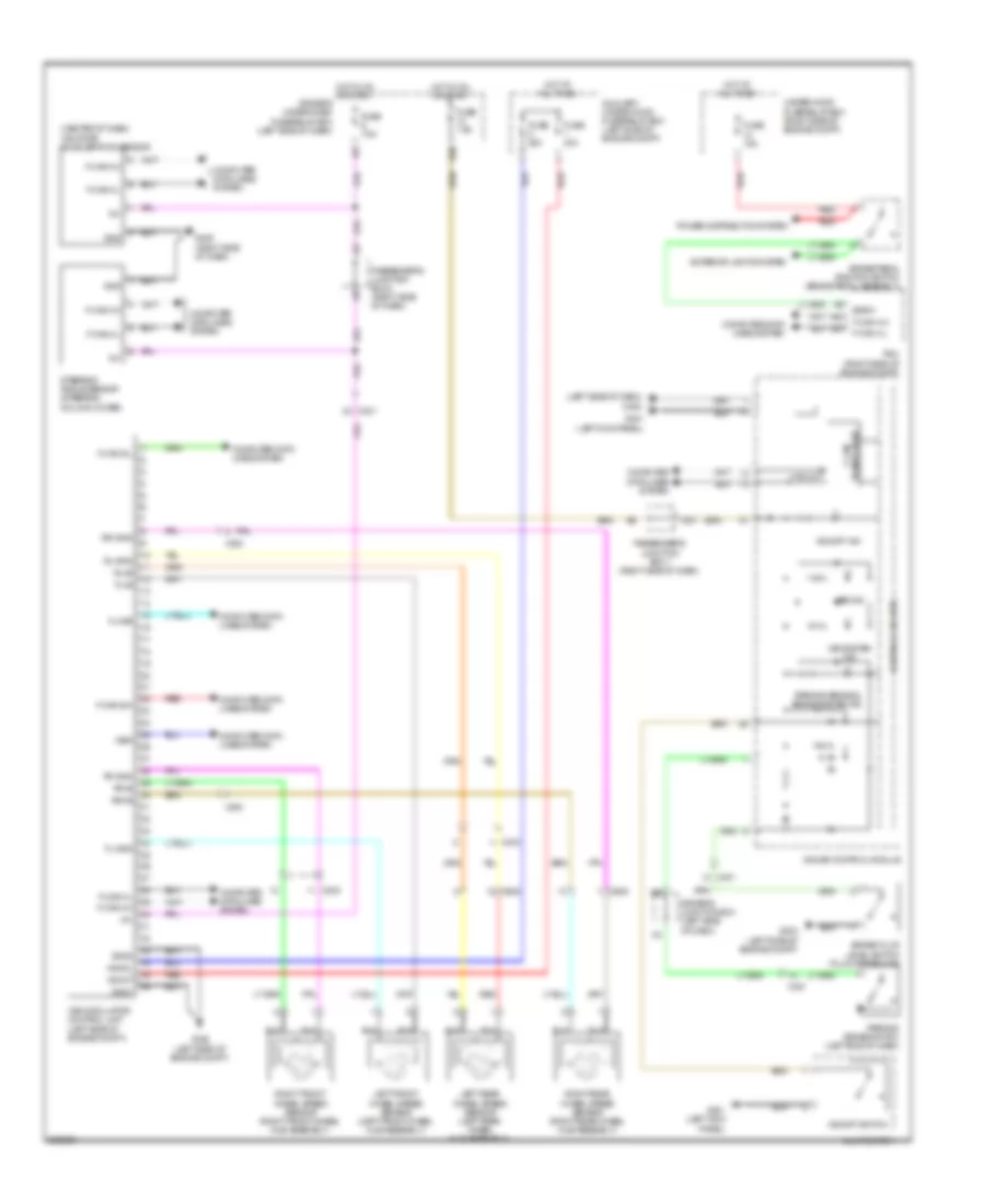
ANTI-LOCK BRAKES
Anti-lock Brakes Wiring Diagram for Acura ZDX 2013
List of elements for Anti-lock Brakes Wiring Diagram for Acura ZDX 2013:
- (center of dash) yaw rate- acceleration sensor
- (left side of dash) g402
- +b mot
- +b sol
- A48
- A49
- Abs ind
- Auxiliary under-hood fuse/relay box (left side of engine compt)
- Bksw
- Brake fluid level switch (fluid reservoir)
- Brake pedal position switch (brake pedal assembly)
- C202
- C301
- C303
- C608
- Computer data lines system
- Control circuits
- Driver's junction box (left side of dash)
- Driver's under-dash fuse/relay box (left side of dash)
- E10
- Exterior lights system
- F-can a h
- F-can a l
- F-can b h
- F-can b l
- F-can transceiver
- Fl+b
- Fl-gnd
- Fr+b
- Fr-gnd
- Fuse 15a
- Fuse 20a
- Fuse 40a
- Fuse 7.5a
- G302 (left side of engine compt)
- G303 (left side of engine compt)
- G401 (left kick panel)
- G405 (right side of dash)
- Gauge control module
- Gnd
- Gnd1
- Gnd2
- Hot at all times
- Hot in on or start
- Ig1
- K-line
- Left front wheel speed sensor (left front wheel hub assembly)
- Left rear wheel speed sensor (left rear wheel hub assembly)
- Multi switch
- P20
- Parking brake & brake system ind
- Parking brake switch (left end of dash)
- Passenger's junction box 1 (right side of dash)
- Passenger's junction box 2 (right side of dash)
- Pcm (right side of engine compt)
- Power distribution system
- Red
- Right front wheel speed sensor (right front wheel hub assembly)
- Right rear wheel speed sensor (right rear wheel hub assembly)
- Rl+b
- Rl-gnd
- Rr+b
- Rr-gnd
- Steering angle sensor (steering column cover)
- Under-hood fuse/relay box (right side of engine compt)
- Vsa modulator- control unit (left side of engine compt)
- Vsa off ind
- Vsa off switch
- Vsa system ind
- Wen
 English