ANTI-LOCK BRAKES
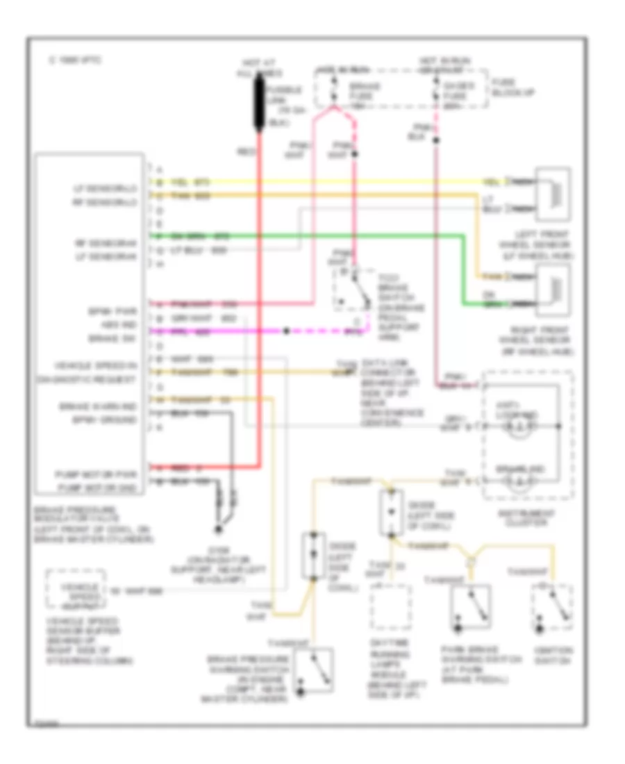
Anti-lock Brake Wiring Diagrams for Chevrolet Astro 1995
List of elements for Anti-lock Brake Wiring Diagrams for Chevrolet Astro 1995:
- (16 ga-
- (behind left side of i/p)
- (in engine
- (lf wheel hub)
- (rf wheel hub)
- Abs ind
- Anti- lock ind.
- Bpmv ground
- Bpmv pwr
- Brake fuse 15a
- Brake ind.
- Brake pressure modulator valve (left front of cowl, on brake master cylinder)
- Brake pressure warning switch
- Brake sw
- Brake warn ind
- C 1995 vftc
- Cluster
- Compt, near
- Data link connector
- Daytime
- Diagnostic request
- Diode (left side of cowl)
- Fuse block:i/p
- Fusible
- G108 (on radiator support, near left headlamp)
- Gages fuse 20a
- Hot at all times
- Hot in run
- Hot in run or start
- Ignition switch
- Instrument
- Left front wheel sensor
- Lf sensor-hi
- Lf sensor-lo
- Link
- Master cylinder)
- Nca
- Output
- Park brake warning switch (at park brake pedal)
- Pnk/
- Pump motor gnd
- Pump motor pwr
- Red
- Rf sensor-hi
- Rf sensor-lo
- Right front wheel sensor
- Running lamps module
- Speed
- Tan
- Tan/
- Tcc/ brake switch (on brake pedal support arm)
- Vehicle
- Vehicle speed in
- Vehicle speed sensor buffer (behind i/p, right side of steering column)
 English