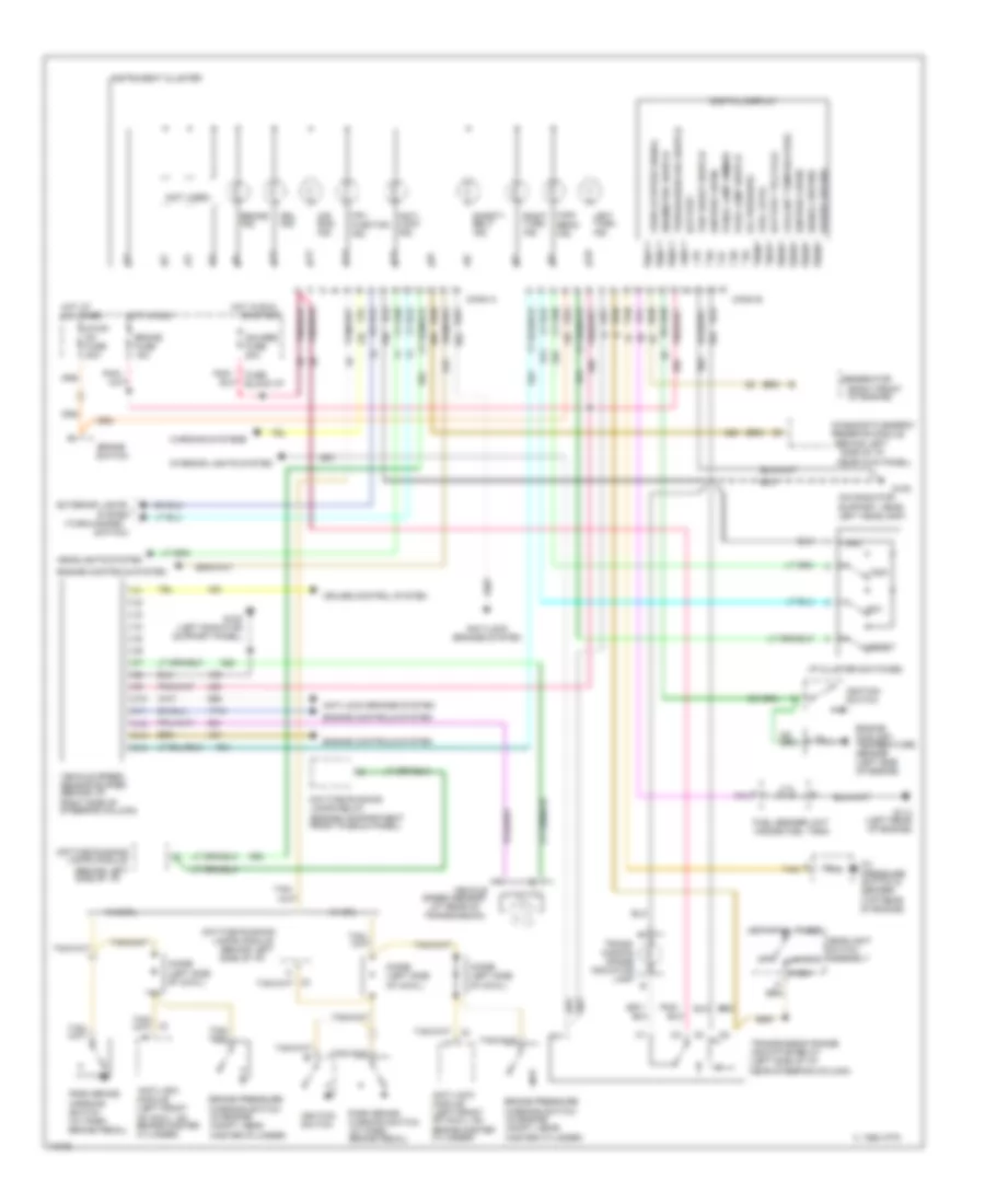
INSTRUMENT CLUSTER
Instrument Cluster Wiring Diagram, Analog for Chevrolet Astro 1995

List of elements for Instrument Cluster Wiring Diagram, Analog for Chevrolet Astro 1995:
- (behind left
- (behind left side of i/p)
- (behind right
- (headlight
- (in engine compt front plenum panel)
- (left front of cowl, on
- (left rear of engine)
- (on radiator support, near left headlamp)
- (turn-hazard
- 1995 vftc c
- A11
- A12
- A13
- A14
- A15
- A16
- A17
- A18
- Air bag ind.
- Anti-lock
- Anti-lock brakes ind.
- Anti-lock brakes system
- Anti-lock module (left front of cowl, on brake master cylinder)
- Audio alarm
- B10
- B11
- B12
- B14
- Battery ind.
- Brake fuse 15a
- Brake ind.
- Brake master
- Brake pressure warning switch (in engine compt, near master cylinder)
- C10
- C11
- C12
- C13
- C14
- Center)
- Conn a
- Conn b
- Control module
- Convenience
- Coolant temperature gauge
- Cruise control system
- Cylinder)
- Daytime
- Daytime running
- Daytime running lamps relay
- Dimmer switch)
- Diode (left side of cowl)
- Drl ind.
- Engine controls system
- Engine coolant temperature sensor (left side of engine)
- Exterior lights
- Fuel gauge
- Fuel sender unit (inside fuel tank)
- Fuse block: i/p
- G108
- G108 (left radiator support panel)
- G114
- Gauges fuse 20a
- Headlights system
- High beam ind.
- Hot in run
- Ignition switch
- Illum. lamps
- Instrument cluster
- Interior lights
- Kick panel)
- Lamps module
- Left turn ind.
- Mal- function ind.
- Module
- Oil pressure gauge
- Oil pressure switch & sender (top rear of engine)
- Only
- Or start
- Park brake warning switch (at park brake pedal)
- Powertrain
- Right turn ind.
- Running lamps module (behind left side of i/p)
- Safety belt ind.
- Side of i/p, in
- Speedo- meter
- Starting/charging system
- Switch)
- System
- Tan
- Vehicle speed sensor (rear of transmission)
- Vehicle speed sensor buffer (behind i/p, right side of steering column)
- Volt- meter
- W/ drl
- W/o drl
Instrument Cluster Wiring Diagram, Digital for Chevrolet Astro 1995
List of elements for Instrument Cluster Wiring Diagram, Digital for Chevrolet Astro 1995:
- (at rear of
- (behind left side of i/p)
- (behind left side of i/p,
- (engine compartment front plenum panel)
- (not used)
- (on radiator support, near left headlamp)
- (right front
- (top rear of engine)
- (turn-hazard
- 1995 vftc c
- A10
- A11
- A12
- A13
- A14
- Air bag ind.
- Anti- lock ind.
- Anti-lock brakes system
- Anti-lock module (left front of cowl, on brake master cylinder)
- B10
- B11
- B12
- B13
- B15
- B16
- Battery
- Battery telltale
- Brake fuse 15a
- Brake ind.
- Brake pressure warning switch (in engine compt, near master cylinder)
- Brake switch
- C10
- C11
- C12
- C13
- C14
- Conn a
- Conn b
- Coolant temperature
- Cruise control system
- Daytime running
- Daytime running lamps relay
- Diagnostic energy
- Digital display
- Diode (left side of cowl)
- Drl ind.
- E/m
- Eng/metric switch
- Engine controls system
- Engine coolant temperature sensor (left side of engine)
- Exterior lights
- Fuel level
- Fuel sender unit (inside fuel tank)
- Fuse block:i/p
- G108
- G108 (left radiator support panel)
- G114 (left rear of engine)
- Gauges fuse 20a
- Generator
- Gnd
- Head
- Headlight switch assembly
- Headlights system
- High beam ind.
- Hot at all times
- Hot in run
- I/p cluster switches
- Ignition 3 (run)
- Ignition switch
- Instrument cluster
- Interior lights system
- Lamps module
- Left turn ind.
- Mal- function ind.
- Near kick panel)
- Of engine)
- Off
- Oil pressure
- Oil pressure switch & sender
- Or start
- Panel lamp dimmer
- Park
- Park brake warning switch (at park brake pedal)
- Park lamp switch
- Pnk/
- Power ground
- Reserve module
- Reset
- Right turn ind.
- Safety belt ind.
- Signal ground
- Speed sensor
- Stop/ hz fuse 20a
- Switch)
- System
- Tan
- Tan/
- Trans- mission range indicator lamp b
- Transmission range indicator relay (left side of i/p, near steering column)
- Transmission)
- Trip
- Trip reset switch
- Trip/season odo switch
- Vehicle
- Vehicle speed sensor buffer (behind i/p, right side of steering column)
- Vehicle speed signal
- W/ drl
- W/o drl
- Warning systems